Cabinet design and EMC Booksize
12.7 Connection systems
Booksize Power Units
Manual, (GH2), 07/2016, 6SL3097-4AC00-0BP8
723
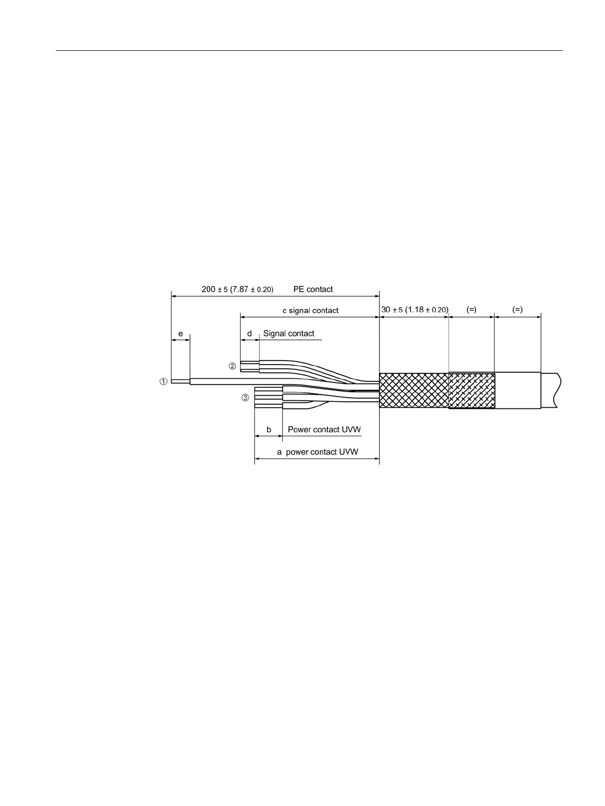
Attaching the motor connector to self-fabricated cables
Preparing the power cable
Non-assembled power cables must be appropriately prepared before the motor connector is
connected.
1. Remove the cable sheath to 200 mm ± 5 mm.
2. Fix the braided shield, e.g. with heat-shrink tubing
3. Remove the insulation from the individual U, V, W conductors and the motor holding
brake connecting cables and shorten these corresponding to the drawing shown below.
4. Remove the insulation from the single PE conductor, and crimp this with a ring cable lug
without insulation (Page 732).
Crimped with ring cable lugs without insulation
Crimped with conductor end sleeves according to DIN 46228-A1.5-10
Crimped with conductor end sleeves according to DIN 46228-E(1.5...10)-12
Lengths depend on mounting a shield connection plate (see below)
Length is dependent on the cable cross-section (see ring cable lug (Page 732))
Figure 12-30 Recommended stripped cable lengths for self-fabricated motor power cables, all data
in mm and (inches)
The following options are available for cable shield support:
● Shield support with shield plate supplied
● Shield support on a toothed rail
● Fixing your own shield support at the shield connection of the motor connector
 Loading...


