Motor Modules Booksize
6.3 Motor Module with external air cooling
Booksize Power Units
Manual, (GH2), 07/2016, 6SL3097-4AC00-0BP8
385
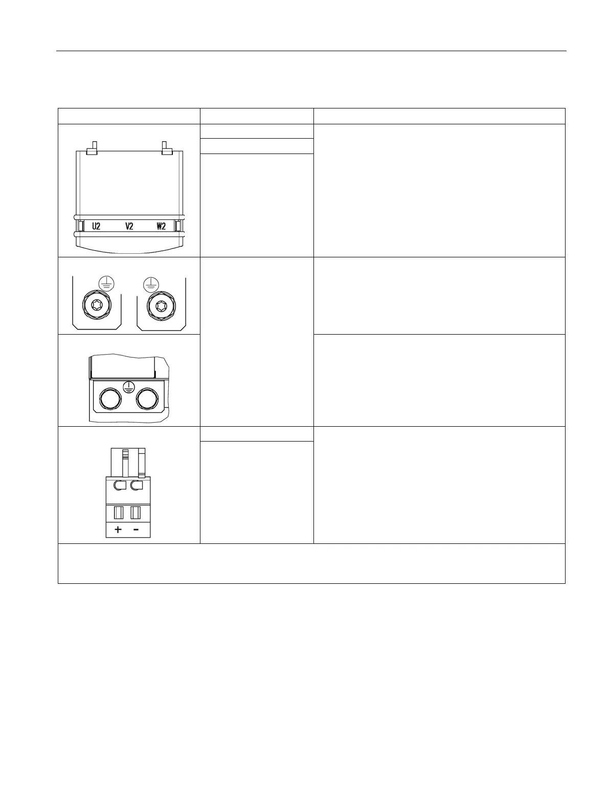
Table 6- 17 X1 motor connection and X11 brake connection for Single Motor Modules 45 A to 200 A
Threaded bolts M6 / 6 Nm
1)
Threaded bolts M8 / 13 Nm
1)
Threaded bolts M8 / 13 Nm
1)
V2
W2
PE connection
Threaded bolts for motor cables: M6 / 6 Nm
1)
Threaded hole for PE: M6 / 6 Nm
1)
Threaded bolts for motor cables: M8 / 13 Nm
1)
Threaded hole for PE: M6 / 6 Nm
1)
Threaded bolts for motor cables: M8 / 13 Nm
1)
Threaded hole for PE: M8 / 13 Nm
1)
2)
:
Supply voltage: 24 V DC ±10 %
Max. load current: 2 A
Minimum load current: 0.1 A
Type: Spring-loaded terminal 2 (Page 730)
The brake connector is part of the prefabricated cable.
- (BR-)
1)
For ring cable lugs without insulation (Page 732)
2)
The circuit for protecting the brake against overvoltage is integrated in the Motor Module and does not need to be in-
Motor holding brake connection
To ensure reliable opening of the motor holding brake, it requires a 24 V ± 10% voltage
supply at the motor connection. It must be taken into account that voltage dips can occur
along the supply cable.
● Use a Control Supply Module or a regulated DC power supply, whose setpoint is set to
26 V.
● Use supply cables with a minimum cross-section of 1.5 mm² and a maximum length of
100 m.
 Loading...


