SIGLENT
20 SDS1000CML+/SDS1000DL+ Quick Start
7. Print function identifier
indicates the print button set to save function
8. Channel identifier
Show the current enabled channel
9. Frequency Counter
Display the firmware frequency of current waveform. To display it,
you should turn on the “Counter” in menu of “UTILITY”.
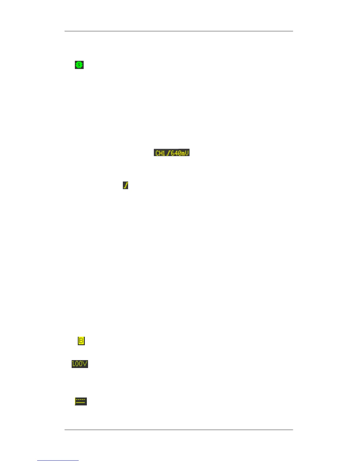
10. Trigger Parameter
Trigger Level. Display the position of the current trigger
level, for example: ;
Trigger Type. Display the current trigger type and trigger
condition. Different trigger types have different marks, for
example: means triggered on Slop side in edge trigger.
11. Trigger Delay Position
Use HORIZONTAL POSITION Knob to modify the parameter.
Turn clockwise or counterclockwise to make the red arrowhead
move right or left, which will respectively cause the decrease
and increase of the parameter in the message box at the
lower-left corner of the screen. Press down the knob to
automatically reset the parameter to zero as well as make the
red arrowhead return to its initial position.
12. Horizontal Timebase
Represent the time of each grid on the horizontal axis of the
screen. You could revolve HORIZONTAL SCALE Knob to
modify the parameter which is variable from 2.5nS to 50S.
13. Channel Parameter
If the current “BW Limit” is “On”, then the mark displays at
the lower-corner of the screen, or nothing displays.
indicates the voltage value of each grid on the vertical axis
of the screen. You could revolve VOLTAGE SCALE Knob
to modify the parameter which is variable from 2mV to 10V.
coupling Mode.The oscilloscope supports three coupling