REXROTH CONTROL SYSTEM
TB24 Plus&26J Plus Maintenance Manual 7-13 © Jun 2022
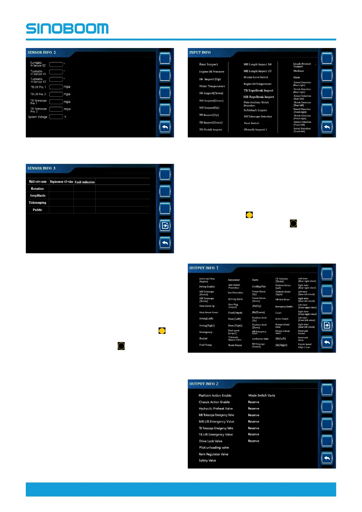
Figure 7-23 SENSOR INFO 2
Figure 7-24 SENSOR INFO 3
Digital input information
• The digital input information option is mainly used to
query the signal detection status of detection
switches (such as travel switches and proximity
switches) configured on the machine (the icon
before the option means that the switch has
detected a signal, and the icon
before the option
means that the switch has not detected a signal),
thus determining whether the detection switches are
working normally and whether the working state of
the machine meets the requirements.
• The configuration of switches is subject to the actual
machine configuration.
Figure 7-25 Input Info interface
Digital output information
• The digital output information option is mainly used
to query the output status of the relays, switching
valves and other output points configured on the
machine (the icon
before the option means that
an output is detected, and the icon
before the
option means that no output is detected), thus
assisting in determining the trouble causes.
• The configuration of output points is subject to the
actual machine configuration.
Figure 7-26 OUTPUT INFO 1 interface