REPAIR PROCEDURES
TB24 Plus&26J Plus Maintenance Manual 6-5 © Jun 2022
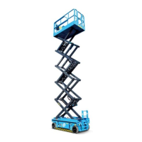
Figure 6-7
5. Retract the boom to 0.6–0.9m (2ft-3ft)of boom
extension.
6. Using a tool, hold the thread end (turntable end) of
the extend cable to prevent it from rotating.
7. Using a wrench, torque alternately the adjusting
nuts of the both extend cables to 112 Nm (82.68 ft-
lb).
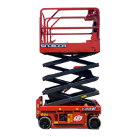
Figure 6-8
8. Fully retract the boom, and ensure each boom
section position dimensions fall within the
tolerances in the figure below.
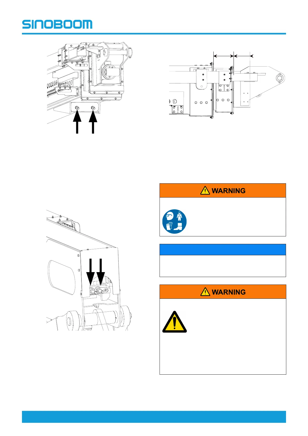
Figure 6-9
9. Re-install the locknut to the steel cable retainer.
10. Check each boom function operates properly.
Main Boom Assembly
MOVING OBJECT HAZARD
Wear eye protection when tapping
the brass drift with a wooden
hammer.
NOTICE
When removing a hose or fitting, the O-ring on the
fitting or hose end must also be removed, replaced
and tagged.
UNSAFE OPERATION HAZARD
Before removing the main boom
assembly and lift cylinder, verify that:
• The boom is positioned in the
chassis drive direction, and the
turntable lock pin is secured, as
shown in Fig 6-9 , page 6-6.
• The counterweight is adequately
supported by a rigid structure, as
shown in Fig 6-10 , page 6-6.
190±15mm
7.5±0.6in
159±15mm
6.3±0.6in