© Jun 2022 5-26 TB24 Plus&26J Plus Maintenance Manual
MAINTENANCE PROCEDURES
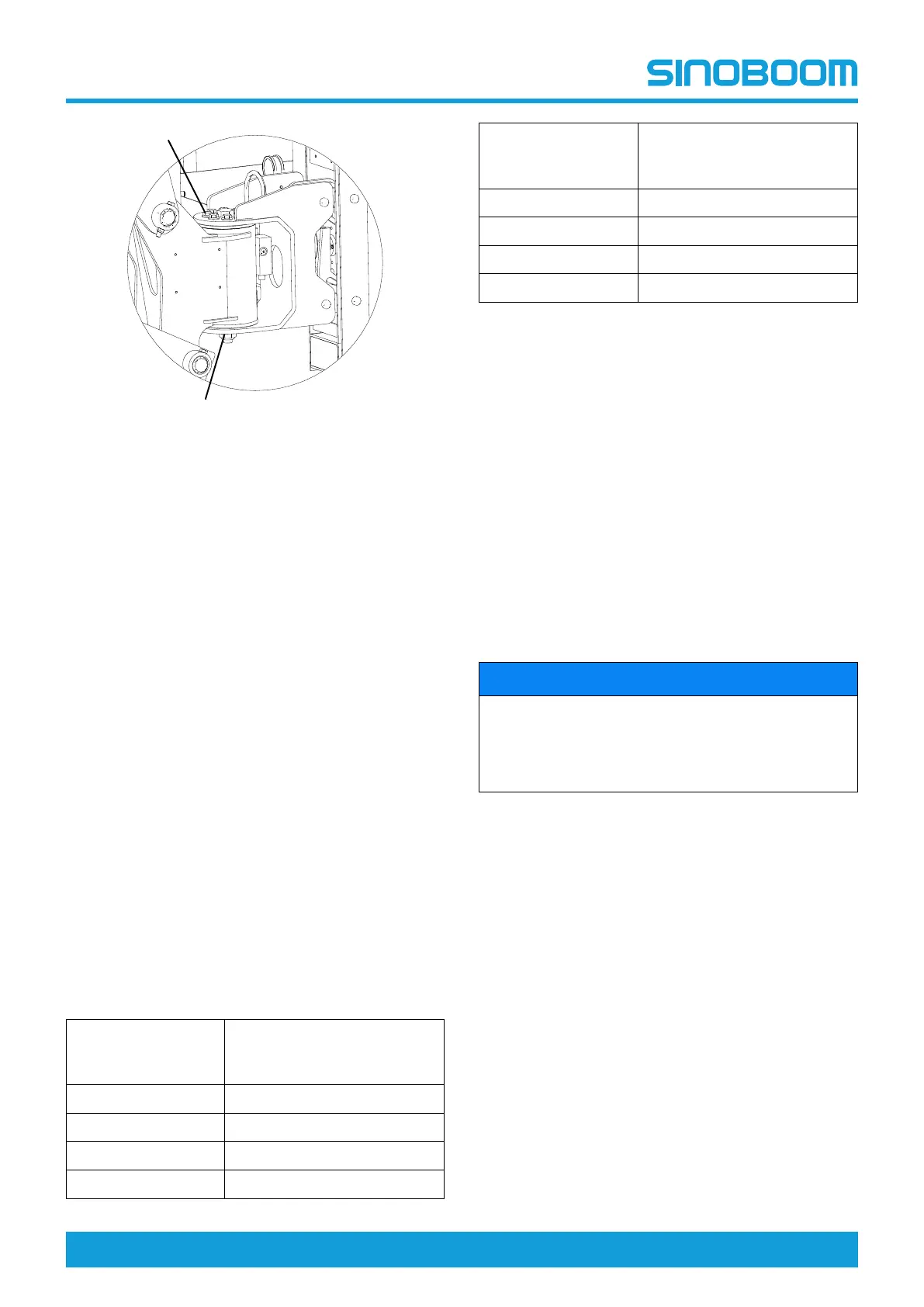
Figure 5-35
1. Place the machine in stowed position.
2. Locate the platform rotate motor.
3. Inspect whether the bolt #1 as indicated in the
above figure is properly torqued to specification
(125Nm[92ft-lb]).
4. If necessary, replace the bolt, torque to specified
value, and apply threadlocker Loctite 272.
5. Inspect whether the nut #2 as indicated in the
above figure is properly torqued to specification
(630Nm[465ft-lb]).
6. If the bolt needs to be replaced, be sure to toruqe to
specification.
B-16 Test Cylinder Drift
Platform drift
Measuring the drift from platform to ground: with rated
load on platform and power off, fully extend the main
boom. The maximum allowable drift in 10 minutes is
50mm (1.97 in). If the test result exceeds this value,
please proceed as below.
Cylinder drift
Table 5-12
Cylinder Bore
Diameter
(mm/in)
Maximum Allowable Drift in
10 Minutes
(mm/in)
63/2.48 0.96/0.037
80/3.15 0.63/0.025
100/3.94 0.39/0.015
125/4.92 0.23/0.009
Cylinder Bore
Diameter
(mm/in)
Maximum Allowable Drift in
10 Minutes
(mm/in)
160/6.30 0.14/0.006
180/7.09 0.13/0.005
200/7.87 0.10/0.0038
220/8.66 0.08/0.0030
• Measure drift at cylinder rod with a calibrated dial
indicator.
• The oil in cylinder must be at ambient temperature
and consistent.
• The cylinder must be applied with normal load from
the platform.
• The cylinder is acceptable if it passes this test.
NOTE: This information is based on 6 drops per minute
cylinder leakage. Since the hydraulic oil expands or
contracts due to thermal effect, thus the test value of
cylinder drift may have a tolerance of 7/10000 for each
temperature change of 1℃.
B-17 Test Counterbalance Valve
Locking
NOTICE
After exhausting the oscillate cylinders, test the
counterbalance valve locking, thereafter test the
oscillate system quarterly, or after replacing any
system component, or when any system malfuction
is discovered.
1. Place a 120mm (4.7 in)wooden block with bevel
side in front of the front left wheel of the machine.
2. Extend the boom by at least 1.2m to place the
machine in operating position.
3. Drive the machine to rest the front left wheel on the
wooden block.
4. Slowly rotate the turntble to the right by 90 degrees.
5. The rear detection indicator light will illuminates,
move the function switches to keep the boom
horizontal and fully extended.
6. Inspect the oscillate cylinder, ensure the oscillate
cylinder on the side with load applied is without any
evidence of retracting, and then retract the boom.
7. Move the reverse drive switch to drive the machine
off the wooden block.
8. The assistant on the ground should inspect whether
the wheel on the front left or rear right still remains
off the ground, and keept it elevated.