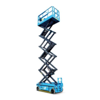
TB24 Plus&26J Plus Maintenance Manual 3-1 © Jun 2022
3 SYSTEM DESCRIPTIONS
POWER SOURCE
The machine is powered by one of the diesel engines
below (optional):
• Cummins QSF2.8t3TC72
• Deutz TD2.9L4
• Deutz TD2011L04i
• WEICHAI WP3.2
• Yuchai YCF3050
The diesel engine drives the oil pump to provide main
power. Two 12V batteries in tandom connection drive a
12V DC motor which boosts the gear pump to provide
auxiliary power for the system.
HYDRAULIC SYSTEM
All functions of the machine are driven by hydraulic
system. The entire hydraulic system can be divided into
two sections: one for boom function, turntable rotating
and steering, driven by a open type variable
displacement pump; the other for chassis driving,
driven by a closed type varible displacement pump.
When the engine operates, the open type displacement
pump works with the electro-proportional flow valve and
solenoid directional valve on the boom function
manifold to control different boom functions; the closed
type variable displacement pump makes a closed
circuit with the drive control valve and the drive motor,
and the electric proportional control handle can control
the machine to drive forward/reverse, with the drive
speed variably controlled. Pressure relief valves are
fitted with the hydraulic system to prevent system
overpressure which may lead to hydraulic component
damage. Also, an emergency power unit is equipped in
the hydraulic system to operate the boom functions in
case of an emergnecy.
ELECTRICAL SYSTEM
Two 12V lead-acid batteries in tandem connection are
used to provide power source for the engine and
auxiliary pump and the electrical system. The batteries
are charged by the DC generator of the engine. Power-
off switches are used to protect the control system.
MACHINE CONTROL
The machine functions are controlled by two
controllers, one installed on the left side of turntable to
control the turnable rotation and boom functions, the
other on the platform to control the machine drive,
turnable rotation and boom functions. The controller
communicates signals through a high-speed data bus.
SAFETY MEASURES
A wide range of sensors and limit switches are used to
provide signals for the controller.
• The level sensor measures the inclinations in X axis
and Y axis of the chassis. When the inclined angle
in X or Y axis exceeds 5°, the alarm will go off and
such functions as lift, drive and steer will be
restricted. Refer to B-23 Inspect Tilt Protection,
page 5-29 for details.
• The length sensor measures the extended boom
length. When the extended boom length exceeds
the maximum allowable horizontal reach, the boom
is restricted from further extending. Refer to B-9
Inspect Length and Angle Sensors, page 5-22 for
details.
• The angle sensor measures the boom luffing angle.
When the boom luffing angle exceeds the limits, the
boom is restricted from further lifting/lowering. Refer
to B-9 Inspect Length and Angle Sensors, page
5-22 for details.
• The weight sensor measures the weight on the
platform. When the weight on the platform exceeds
the rated load, the buzzer will sound continuously,
the overload indicator will flash, the display will
indicate platform overload, the associated functions
will be restricted. Refer to C-6 Inspect Weighing
System, page 5-34 for details.