© Jun 2022 5-16 TB24 Plus&26J Plus Maintenance Manual
MAINTENANCE PROCEDURES
12. Glow plug 24. Axle retracted in place
Note:
1. When the Overload Limit symbol appears, if the platform is overloaded, a series of functions will be restricted if
the machine is in operating position. Details are provided below.
2. When the Drive Limit symbol appears, it indicates the drive function is restricted if the machine is in operating
position.
3. When the Drive & Boom Function Allowed symbol appears, it indicates the drive and boom functions are
allowed to operate simultaneously.
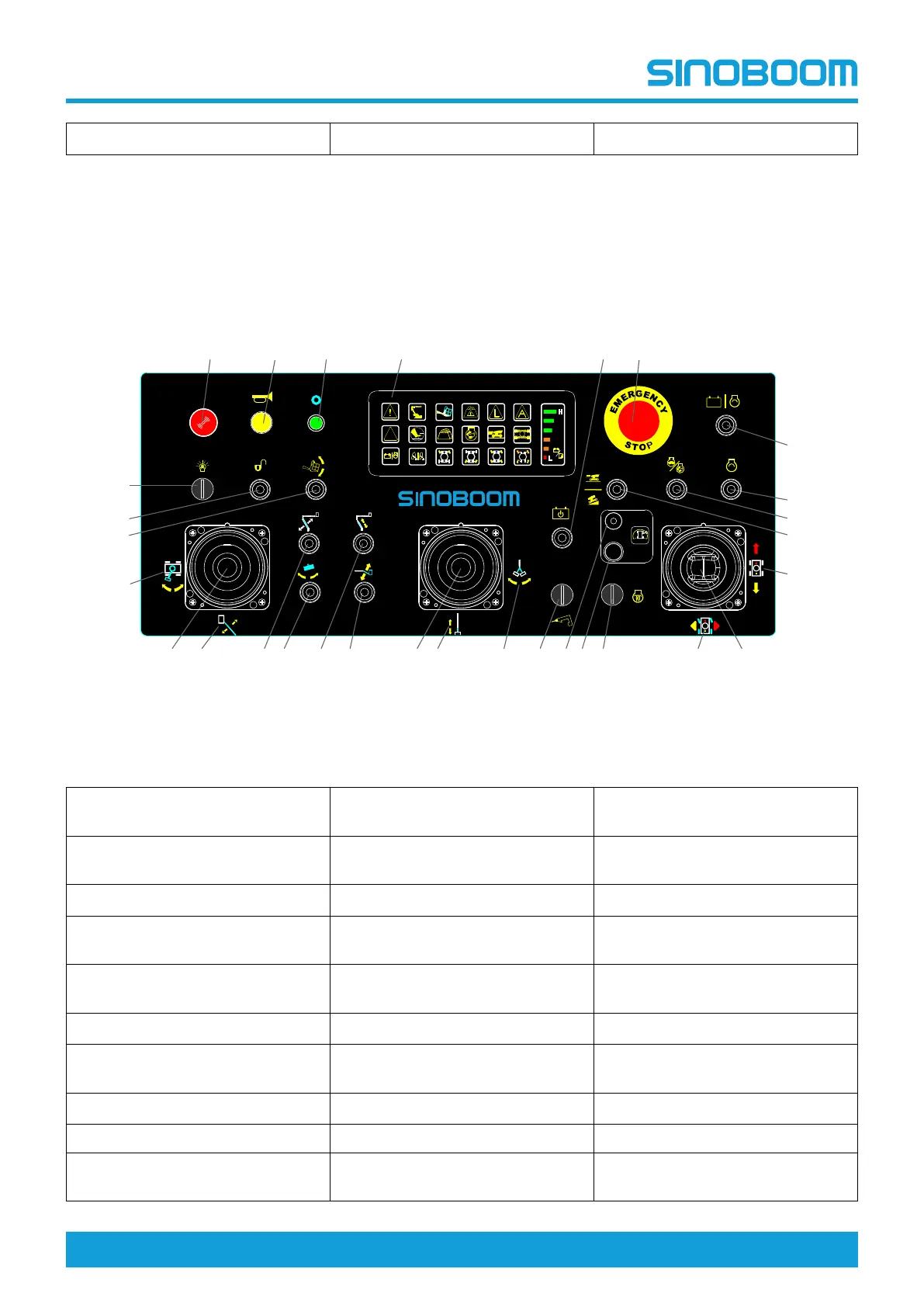
Figure 5-15 Platform Controller
Table 5-11
1. Work light switch
(if equipped)
11. Main boom telescope/jib rotate
control handle
21. Drive high/low speed select
switch
2. Release switch
(if equipped)
12. Main boom telescope direction
22. Engine high/low speed select
switch
3. Platform level switch
13. Jib rotate direction (not used) 23. Engine start switch
4. Turntable rotate direction
14. Hydraulic generator switch
(if equipped)
24. Not used
5. Main boom lift/turntable rotate
control handle
15. Rear position detection indicator
light
25. Emergency stop button
6. Main boom lift direction
16. Rear position travel drive switch 26. Emergency power switch
7. Not used
17. Glow plug switch
(if equipped)
27. Malfunction indicator panel
8. Platform rotate switch 18. Steer direction
28. Power indicator light
9. Not used 19. Drive/steer control handle 29. Horn button
10. Jib up/down switch-TB26J Plus
only
20. Drive direction 30. Buzzer button
CAUTION
- +
DC FE
1
2
3
4
5 6 7 8 9 10 11 12 13 14 15 16 17 18 19
20
21
22
23
24
252627282930
DC
FE
Scope