38
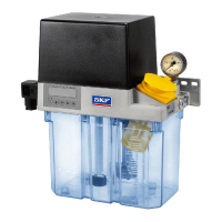
Gear pump units (1) are driven by electric
motors. Depending on the model design,
AC motors or DC motors are used. The basic
design of AC motors is a capacitor motor for
230 V 50/60 Hz and 115 V 50/60 Hz sing-
le-phase alternating current; the basic design
for DC motors is for 24 V direct current.
On a gear pump unit with or without a
control unit, the electrical connection is es-
tablished by the following depending on the
control/monitoring:
o 2 cable glands
o 1 cable gland and a rectangular connector
(XS1) acc. to DIN EN 175301-803-A
o 1 circular connector M12x1 (XS2) and a
rectangular connector acc. to
DIN EN 175301-803-A
o 1 plug and a cable gland
o 1 plug and a rectangular connector acc. to
DIN EN 175301-803-A
In the design with a control unit, the motor
is connected to the electronic control unit.
The wiring is connected in accordance
with the electrical circuit diagrams in
Chapters 4.7 to 4.8.8.
The electrical circuit diagram of the gear
pump unit is affixed inside the unit's cover
cap (2) and can be accessed by removing
the cap.
For a gear pump unit with control
unit, also consult the operating in-
structions for the control unit. This
is included in the accompanying
documentation.
In the case of electric switches with inductive
loads, the inductivity of the switch must be
low in order to keep wear on contact surfaces
to a minimum. Otherwise, there is a risk of
damaging the contact surfaces on the
switch elements. Appropriate measures
must be taken to protect the contacts of
the switch elements.
4.5.2 Electric motor connection with
cable socket and circular plug
See Figure 10
• Connect the connector plug for the cable
socket (XS1) and circular connector (XS2)
provided by customer in accordance with
the wiring diagram affixed to the inside
of the cover cap (see Fig. 7) or the figure
(Fig. 8 to 31) for the type number
• Mount and tighten connector plugs
• Lay the connection cable provided by
customer in a stress-free position
EN
4. Assembly
 Loading...
