78
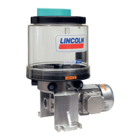
Gear pump units with a control unit contain
a programmable electronic control unit
that can be used to control and monitor the
gear pump unit. Electronic control units are
designed as pulse generators/pulse counters
(contactors/contact counters).
For pulse generators (contactors), the
device determines the length of the interval
by starting at the intervals defined by the
operator.
Depending on the model design, the elec-
tronic control unit allows configuration of
the interval time, pump delay time, and the
number of prelubrication cycles. One or
more prelubrication cycles with short interval
times can be triggered prior to starting up
the machine.
Prelubrication cycles ensure that, prior to
actually starting the machine, a sufficient
quantity of lubricant is built up in the lubricant
lines and distributor or (in oil+air centrali-
zed lubrication systems) a fully developed
oil streak is formed in the lubrication point
lines.
The pump cycle time is 60 seconds and cannot
be changed.
For pulse generators (contact counters),
the interval is determined by the machine,
which sends pulses to the control unit during
operation. The control unit counts the pulses
that are received on the machine contact
(MK or MKPV) and starts a contact time after
the pre-set number of pulses. The operator
can set the number of incoming pulses to be
counted.
Some of the control units provide sup-
port for monitoring devices. The electrical
connection of the monitoring units is estab-
lished at the terminal strip of the electronic
control unit of the gear pump unit. The control
unit directly monitors the operation of the
oil pressure switch, the pressure switch for
minimum air pressure (both possible on
MKL design), and the fill level switch.
Gear pump units with an electronic control
unit are supplied with all internal wiring
fully connected. Depending on the electronic
control
5.4 Gear pump unit with control unit (IG/IZ38, IGZ36, IG54)
unit's model design, a signal line for
fault monitoring can be connected to the
electronic control unit for connection to the
machine control unit.
The signal line is run outwards via a cable
gland mounted on the gear pump unit.
Details on the function and operation of the
electronic control unit can be found in the
assembly instructions for the electronic control
unit, which are included in the scope of
delivery of a gear pump unit.
EN
5. Functional description
 Loading...
