36
WARNING
Risk of slipping
Mark areas that are moist or con-
taminated with lubricant with
appropriate warning signs.
Immediately bind/remove
lubricants.
WARNING
Personal injury/property damage
Drill assembly holes in such a way
that no lines, units, or moving parts
are damaged or their function im-
paired. Maintain safety clearances
and comply with regulations for
assembly and accident
prevention.
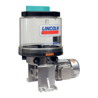
4.4 Attachment of a gear pump unit
See Figures 3 to 6
• Drill assembly holes on the surface accor-
ding to the assembly drawing (assembly
holes, Figs. 3 - 6)
• Clean surface to remove drilling chips;
prime the boreholes if necessary
• Lift the gear pump unit and align it to the
assembly holes
• Pass hexagon head bolts with associated
washers through the fixing holes on
mounting plate
• Apply hexagon nuts (4x) with associated
washers and tighten gently
• Align the gear pump unit horizontally and
vertically
• Tighten hexagon head screws with the
following tightening torque
Torque
M6 = 10 Nm
M8 = 25 Nm
EN
4. Assembly
 Loading...
