75
5
theoretical reservoir capacity (rated capacity)
can be used.
The pressure relief valve mounted in the
gear pump unit is required in order to re-
lieve the system pressure built up during a
lubricating cycle to a residual pressure of
≤ 0.5 bar once the motor is turned off.
This is required for the operation of the
piston distributors.
The pressure-regulating valve mounted in
the gear pump unit is required in order to
limit the maximum permissible system
pressure in the centralized lubrication
system to a maximum value. In the basic
design, the pressure-regulating valve in a
gear pump unit is set to a maximum system
pressure of 30 bar.
Gear pump units are available in model
designs with or without a control unit. In
the model design without a control unit, the
gear pump unit (and thus the lubrication
interval) is controlled by the control unit
of the machine that the gear pump unit is
mounted on. In the model design with a
control unit, the gear pump unit is equipped
with an electronic control unit that controls
the gear pump unit (and thus the lubrication
interval).
In the model designs with or without a
control unit, the electrical connection to
the supply voltage is established using a
rectangular connector (8) as per DIN EN
175301-803-A (clamping range Ø 8 to
10 mm).
In the model design without a control unit,
the electrical connection to monitoring units
such as pressure switches and float switches
is established via a terminal strip. The electrical
line is run outwards via a cable gland (clam-
ping range Ø 6 to 12 mm or Ø 5 - 10 mm)
mounted on the gear pump unit.
In the model design with a control unit, the
electrical connection to the monitoring
units such as pressure switches and float
switches is established inside the gear
pump unit directly to the connectors on the
5.2 Structure of a gear pump unit
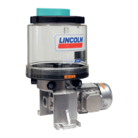
See Figure 1
In the basic design, gear pump units con-
tain an electrically driven gear pump (1), a
lubricant reservoir (2 (plastic = 2-, 3-, and
6-liter rated capacity; metal = 3-liter
rated capacity), a pressure switch (3) for
electrical pressure monitoring, a fill level
switch (4) for monitoring the minimum fill
level, and a pressure gauge (5) for visual
pressure monitoring.
A pressure relief valve and a pressure-regu-
lating valve are also mounted inside the gear
pump unit. The filler socket (6) is accessible
from outside the unit and is equipped with a
filler screen (7) (only on gear pump units for
oil lubrication).
The plastic reservoirs consist of transparent
plastic that allows visual inspection of the
fill level. The metal reservoirs (only on the
oil design) contain a fill level indicator that
likewise allows visual inspection of the fill
level. Due to the components built into the
reservoir, only a maximum of 80% of the
4
EN
5. Functional description
 Loading...
