41
4
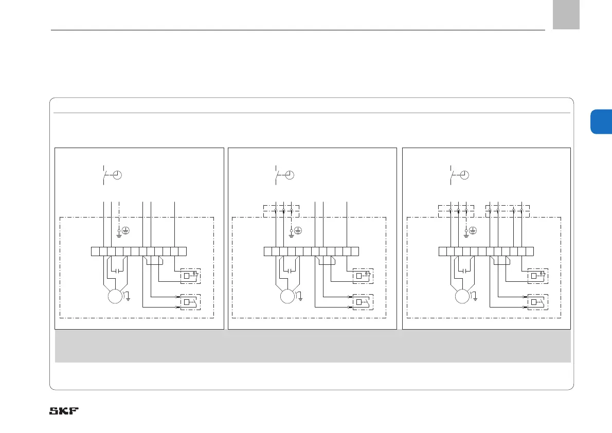
4.7 Terminal diagrams for MKU/MKF, without control unit
4.7.1 MKU, 2-liter reservoir, voltage design 230/115 VAC, without pushbutton
MKU, 2-liter reservoir, voltage design 230 VAC/115 VAC, without pushbutton, Fig. 11
Connections via:
BU
BN
BK
1 32 4 5 6
P
Q
GY
GY
BK
BK
87 9 1210 11
1~
MKU1-11A _ _ 2000+428/+429MKU1-11A _ _ 1000+428/+429
MKU1-11A _ _ 4000+428/+429
1)
MKU1-11A _ _ 0000+428/+429
MKU1-11A _ _ 3000+428/+429
1)
2)
N
L1/S
PE
1 2
BU
BK
PE
+24V DC PELV
DS Signal
WS Signal
1 4 2
BN
BK
WH
3
BU
GNYE
230V/115V 50/60Hz
L1
BU
BN
BK
1 32 4 5 6
P
Q
GY
GY
BK
BK
87 9 1210 11
1~
1)
1)
2)
N
L1/S
PE
1 2
BU
BK
PE
+24V DC PELV
DS Signal
WS Signal
GNYE
230V/115V 50/60Hz
L1
BU
BN
BK
1 32 4 5 6
P
Q
GY
GY
BK
BK
87 9 1210 11
1~
1)
1)
2)
N
L1/S
PE
+24V DC PELV
DS Signal
WS Signal
GNYE
230V/115V 50/60Hz
L1
951-115-001
951-115-002
951-115-003
C
M
DS
WS
X1
XS1
XS2
C
M
DS
WS
X1
XS1
C
M
DS
WS
X1
1) Optional See Chapter 4.6.1 for legend to the terminal diagrams
2) Optional: Contact closes at minimum level (NO)
2x cable glands
1x XS1 connector (DIN EN 175301-803 A)
1x cable gland
XS1 connector (DIN EN 175301-803 A)
XS2 plug (M12x1)
EN
4. Assembly
 Loading...


