40
Description and legend
Legend:
M = Pump motor
C = Capacitor
L1/S/N = Connection for operating
voltage
PE = Protective earth conductor
WS = Fill level switch
DS = Pressure switch
DK = Pushbutton for interim
lubrication
SL = Indicator lamp (green)
“Operation”
SL1 = Indicator lamp (green)
“Operation”
SL2 = Indicator lamp (red) “Fault”
XS1 = Plug connector acc. to
DIN EN 175301-803 A
XS2 = Plug connector M12×1X1
MK = Machine contact
DL = Air pressure switch
Y1 = Compressed air valve
F = Fuse
(on 24 VDC designs)
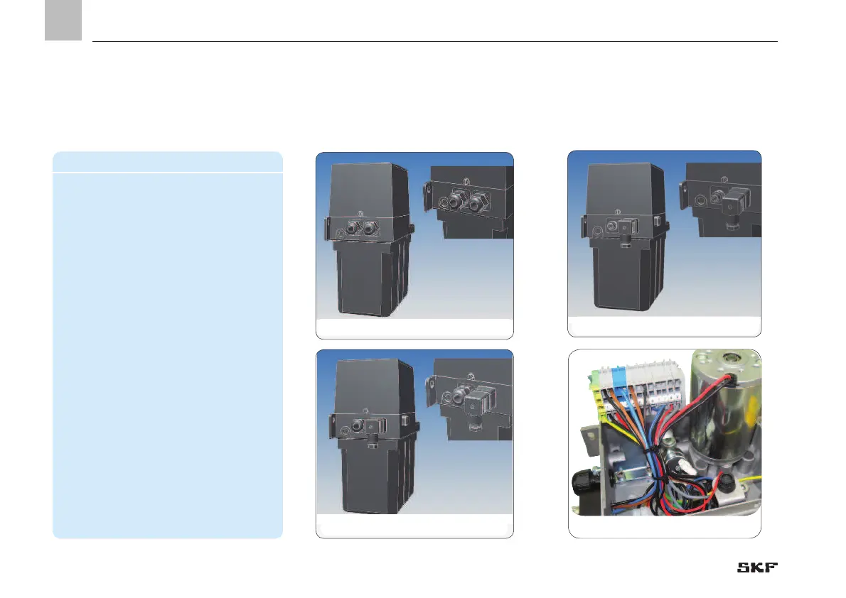
4.6 Terminal diagrams
4.6.1 Legend to the terminal diagrams
2x cable glands
XS1 connector, XS2 connector
XS1 connector, cable gland Terminal strip, item 1 to 9
EN
4. Assembly
 Loading...


