39
4
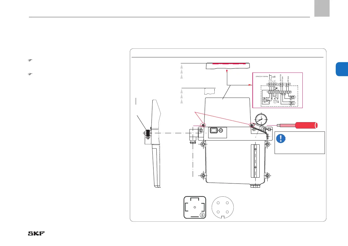
4.5.3 Electric motor connection with
cable glands
See Figure 10
The cover cap (1) is secured by two
slotted screws (2).
• Loosen but do not unscrew (!) the slotted
screws (2) from the cover cap (1) using a
screwdriver.
• Carefully lift the cover cap (1) and put it
aside
• Loosen the cable gland (3)
• Insert the connection cable provided by
the customer into the cable gland (3)
• Connect the connection cable provided by
customer in accordance with the wiring
diagram affixed to the inside of the cover
cap (see Fig. 7) or the figure (Fig. 8 to 31)
for the type number
• Tighten the cable gland (3)
• Carefully apply the cover cap (1) and
fasten the slotted screws (2) finger-tight
with equal force
• Lay the connection cable provided by
customer in a stress-free position
2
3
1
XS1
 Loading...


