28
4.2.1 Minimum mounting dimensions
The mounting position of the gear pump unit
is vertical as shown in this documentation.
The fill level of the lubricant reservoir,
pressure gauges, oil level glasses, and
other visual monitoring equipment must be
clearly visible.
Any assembly holes must be made according
to the diagram on the following page.
During assembly and especially when drilling,
always pay attention to the following:
o Existing supply lines must not be damaged
by assembly work.
o Other units must not be damaged by as-
sembly work.
o The gear pump unit must not be installed
within range of moving parts.
o The gear pump unit must be installed at
an adequate distance from sources of
heat.
o Maintain safety clearances and comply
with local regulations for assembly and
accident prevention.
Fastening material to be provided by the
customer:
- see the respective assembly drawing
To ensure enough space for maintenance
work and possible disassembly of the gear
pump unit, ensure that the minimum
mounting dimensions (Figs. 3 to 6) are
maintained.
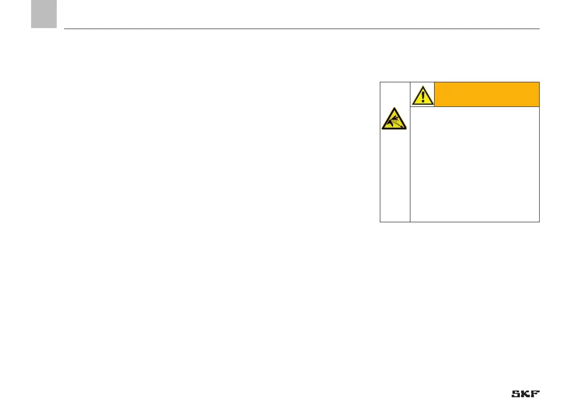
WARNING
System pressure
The fittings used to connect the
lubrication line should be rated for
the maximum operating pressure
of the lubrication unit. If they are
not, the lubrication line system
needs to be protected from
excessive pressure by means of a
pressure-limiting valve.
EN
4. Assembly
 Loading...


