92
Section 5 – Procedures Electronic Tilt Switch Setup Procedure
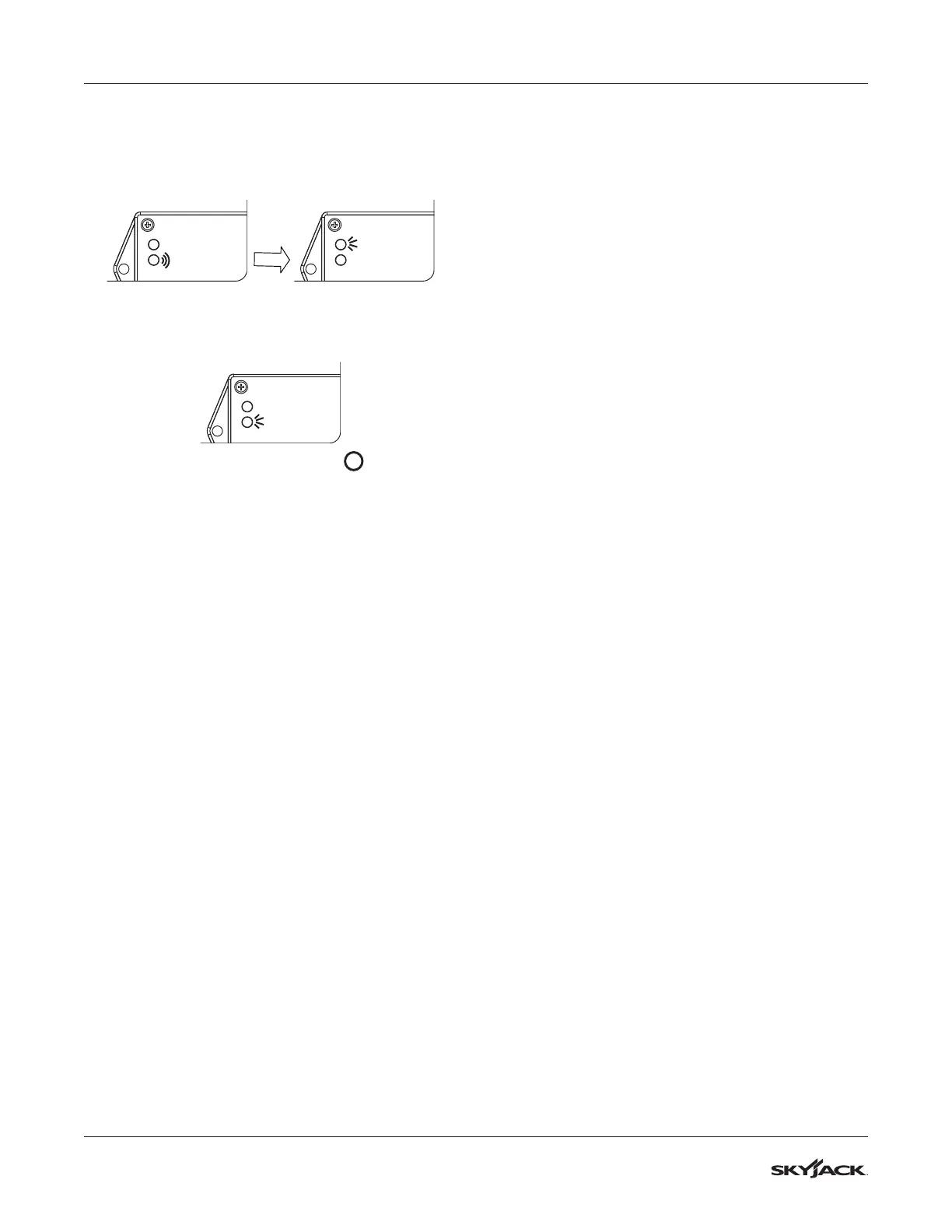
E. The green LED will ash and then the
red LED will turn on solid for 2 seconds.
Results: The switch is verifying the new zero
position.
Red LED
Green LED
Red LED
Green LED
F. The green LED will turn on solid.
Results: The switch is ready for normal
operation.
Red LED
Green LED
15. Turn main disconnect switch to “ ” off position.
16. Remove jumper wire between #7 and #19 from
terminal block.
17. Reattach all wires #02 to motor contactor.
18. Reinstall cover plate on the base control
console. Reinstall the base control console into
the base of the machine and secure with old
hardware.
19. Reinstall any covers that were removed.
20. Close the base cover making sure it is secure.
Retract the transverse deck to the stored
position.
21. Remove chock or wheel blocks.
22. Proceed to Test and Verify Tilt Circuit.