94
Section 5 – Procedures Electronic Tilt Switch Setup Procedure
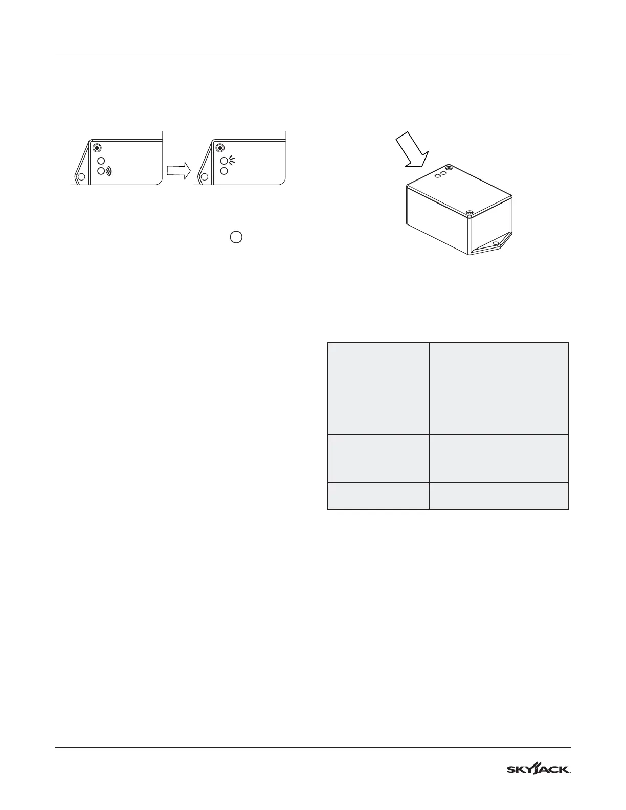
H. The green LED will flash and then the red
LED will turn on solid for 2 seconds.
Results: The switch is verifying the new zero
position.
Red LED
Green LED
Red LED
Green LED
I. The green LED will turn on solid.
Results: The switch is ready for normal
operation.
12. Turn main disconnect switch to “ ” off
position.
13. Remove jumper wire between #7 and #19 from
terminal block.
14. Reattach all wires #02 to motor contactor.
15. Reinstall cover plate on the base control
console. Reinstall the base control console into
the base of the machine and secure with old
hardware.
16. Reinstall any covers that were removed.
17. Close the base cover making sure it is secure.
Retract the transverse deck to the stored
position.
18. Remove chock or wheel blocks.
19. Proceed to Test and Verify Tilt Circuit.
5.4-3 Test and Verify Tilt Circuit
Red LED
Green LED
Indicators Lights
Operations of Tilt Switch
The following describes the LED’s and what they
indicate.
Green LED
Illuminated whenever both tilt
axes are within the specified
degrees of the zero/ home
learned position.
Flashes when transitioning in
or out of tilt angle limits, but
built in time delay has not fully
occurred.
Red LED
Illuminated whenever tilt on one
or more axes is more than the
specified degrees out from the
zero/ home position.
Green & Red LED
On together, no blinking when
fault detected.
Tilt Circuit Test
1. Refer to section 2 for test tilt sensor procedure.