5 Product Overview
SMA Solar Technology AG
Operating manualHM-20-BE-en-1916
5 Product Overview
5.1 Product Description
A
E
B
C
R
eset
SUNNY HOME MANA
GER 2.0
Figure 2: Sunny Home Manager 2.0
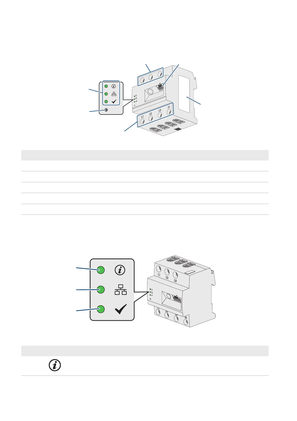
Position Designation
A Connection area for line conductors and neutral conductor
B Light-emitting diodes
C Reset button
D Network terminal (Speedwire/Ethernet)
E Type label
5.2 Symbols on the Product
5.2.1 Light-Emitting Diodes (LEDs)
The LEDs indicate the operating state of the product.
R
eset
SUNNY HOME MANA
GER 2.0
A
B
C
Figure 3: LEDs of the SunnyHomeManager
Position LED symbol Designation Explanation
A Status LED Displays the operating state of the SunnyHomeManager (op-
eration, startup process, error status)