8 Connection
SMA Solar Technology AG
Operating manualHM-20-BE-en-1924
8.2.2 Connecting the Voltage Supply up to 63A
L1 L2 L3
NL1 L2 L3
L1 L2 L3
L1 L2 L3
N
Ethernet
OUT
IN
N
Household
Disconnect switch
Energy meter of
the electric
utility company
Main breaker
(three-phase)
Utility grid
Inverters
Sunny Home Manager 2.0
as purchased electricity
and feed-in meter
Delta-IT
3 phase TN/TT 1 phase TN/TT
Split Phase
Radio
Neutral conductor
Line conductor
Meter output, load side
Meter input, grid side
L1/L2/L3
N
OUT
IN
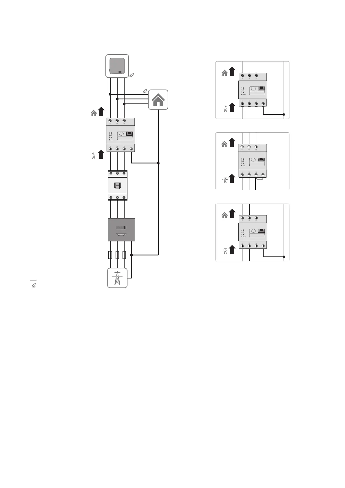
Figure 5: The following figure shows a connection example in TN and TT utility grids in the case of installation at the grid-connection point when
using the integrated measuring unit.
Procedure:
1. Disconnect the connection point from voltage sources and make sure it cannot be reconnected.
2. Connect the line conductors depending on the utility grid conditions to the SunnyHomeManager as follows:
- in Three-phase utility grids connect the line conductors L1, L2, L3 and the neutral conductor N to the screw
terminals at the input of the SunnyHomeManager.
- in Single-phase utility grids connect the line conductor L1 and the neutral conductor N to the screw terminals
at the input of the SunnyHomeManager.
- in Delta IT utility grids connect the line conductors L1, L2 and L3 to the screw terminals at the input of the
SunnyHomeManager. In addition, also connect the line conductor L3 to the neutral conductor N.
- in Split phase grids (split-phase system) connect the line conductors L1 and L2 and the neutral conductor N to
the screw terminals at the input of the SunnyHomeManager.
Open each screw terminal using a cross-head screwdriver, insert the conductor into the contact terminal and
tighten the screw (torque: 2.0Nm).
If you do not want to use the SunnyHomeManager - as provided by default - as a bi-directional device, but should
opt for only one of its two functions, the SunnyHomeManager must be connected as follows: