8 Connection
SMA Solar Technology AG
Operating manual 27HM-20-BE-en-19
☐ Cable type: 100BaseTx
☐ Cable category: minimum CAT5e
☐ Plug type: RJ45 of Cat5, Cat5e, Cat6 or Cat6a (Cat7 plugs cannot be used)
☐ Shielding: S/UTP, F/UTP or higher
☐ Number of insulated conductor pairs and insulated conductor cross-section: at least 2 x 2 x 0.22 mm²
☐ Maximum cable length between 2 nodes when using patch cables: 50m
☐ Maximum cable length between 2 nodes when using installation cables: 100m
☐ UV-resistant for outdoor use.
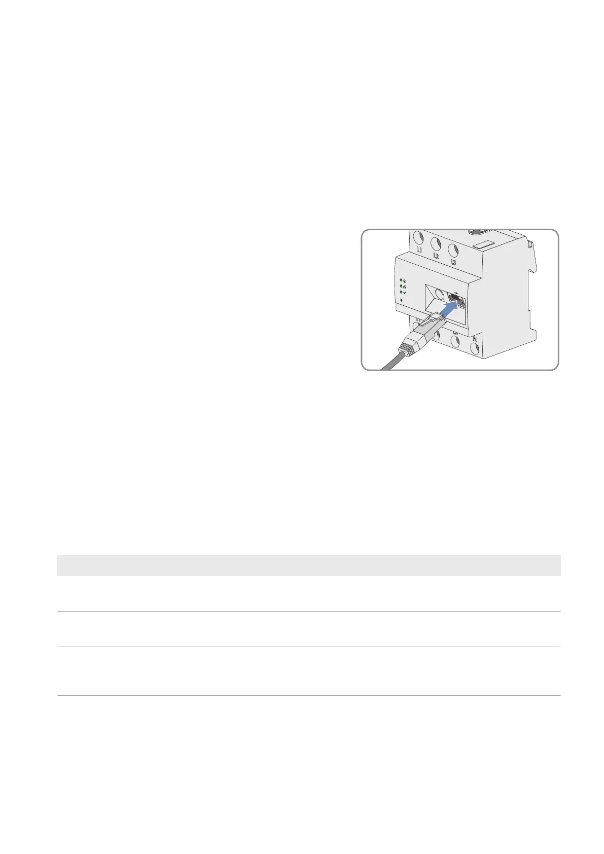
Procedure:
1. Connect the network cable to the network terminal of the product.
R
eset
SUNNY HOME MANA
GER 2.0
2. Connect the other end of the network cable to the router.
8.3.3 Testing the Connection to SunnyPortal
The SunnyHomeManager automatically establishes a connection to SunnyPortal.
Requirements:
☐ The SunnyHomeManager must be supplied with voltage.
☐ The SunnyHomeManager must be connected to the router.
☐ DHCP must be active for the router (see router manual). If your router does not support DHCP, you can configure
the static network settings on the SunnyHomeManager using the SunnyHomeManagerAssistant (see
Section18.6, page130).
The display of the LEDs serves as control:
Status display LED Explanation
Status LED: glowing green
Performance LED: glowing green
There is in active connection to SunnyPortal and the registration in SunnyPortal
has already been executed.
Status LED: glowing green
Performance LED: off
The connection to SunnyPortal has been established, but the SunnyHomeMan-
ager must still be registered in the portal.
Status LED: flashing red
or
Performance LED: flashing red
The SunnyHomeManager cannot establish the connection to SunnyPortal auto-
matically.