HRX-MM-N007
Chapter 3 Alarm Indication and Troubleshooting
HRS Series 3.3 Troubleshooting
1. Check the connection
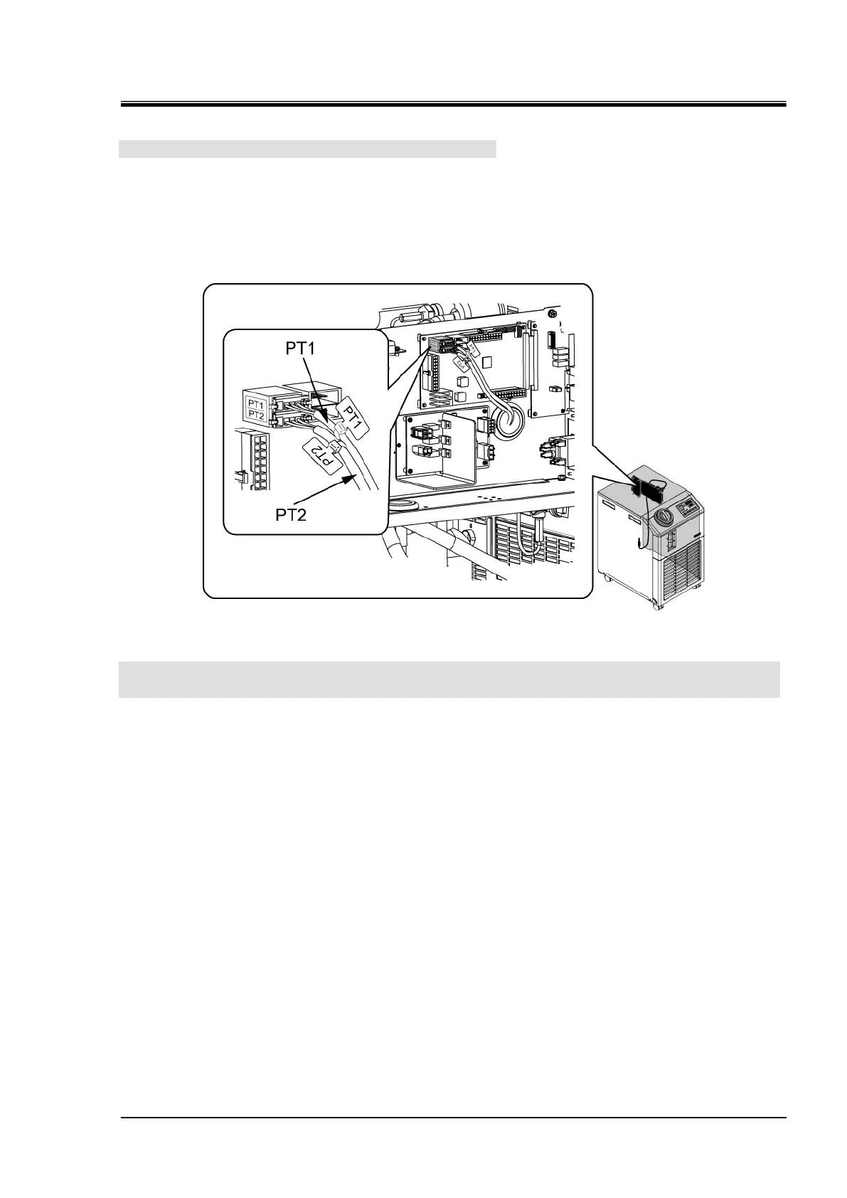
Check the circulating fluid temperature sensor (for discharge) "PT1" that is connected to the main
board for the items shown below:
(1) The connector is securely connected.
(2) The pins are securely inserted and there is no defective crimping. Check for the correct
connection by lightly pulling the cable.
2. "AL23" goes off when the cables that are connected to PT1 and PT2 are exchanged
and connected.
Perform checking with the Thermo-Chiller not operating. Check if "AL22" is reset and "AL23" is
generated by taking the following instructions:
(1) Exchange the inserting position of the connector "PT1" for circulating fluid temperature sensor
(for discharge) and the connector "PT2" for circulating fluid temperature sensor (for return).
(2) Reset the alarm.
(3) Check if the cables inserting position exchange resets "AL22" and generates "AL23".
Fig. 3.3-70 Check for the correct
connection of PT1
 Loading...


