HRX-MM-N007
Chapter 3 Alarm Indication and Troubleshooting
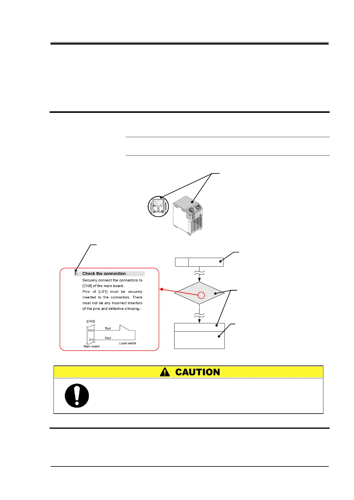
HRS Series 3.3 Troubleshooting
See section "4.5.16
Replacement of main board
& communication board".
Y
Low level in tankAL01
Replace the main board.
1.
Check of the correct
connections
3.3 Troubleshooting
3.3.1 How to use the flow chart of troubleshooting
1. Find a flow chart of troubleshooting corresponding to the error, referring to table
3-1 “Error Type and Alarm Set Value”.
2. Troubleshoot a problem through an item-by-item check in the flow chart.
[Tips]
Go through the items of guidelines from top down for troubleshooting.
No items are to be skipped unless otherwise specified.
Example:
3. See “Chapter 4 Service Procedure” for actual replacement of units.
Check, replacement or repair item
Page number in which the procedure
for replacement or repair is defined.
(in Chapter 4 “Service Procedure”)
Important notes for check and
inspection in the flow chart
are provided at the end.
Alarm code and error message
The removable panel as well as tools
required for check and inspection are
indicated by icons.
See section 3.3.2 “Required Tools and
Icons” for details.
Replacement or repair of the refrigerant circuit parts must be
performed by a specialized operator.
Any operators other than specialized operators must not replace or
repair the refrigerant circuit including the parts.
 Loading...


