HRX-MM-N007
Chapter 4 Service Procedure
4.5 Replacement Procedure HRS Series
4.5 Replacement Procedure
4.5.1 Replacement of temperature sensor (PT1)
<HRS-A/W->
Table 4-5 Part number of service parts (Temperature sensor)
Removal
1. Discharge the circulating fluid referring the 4.2.2 Discharge of the circulating fluid and
facility water.
2. Remove the upper panel and the side panel on the right referring the 4.2.1 Removal and the
mounting of the panel.
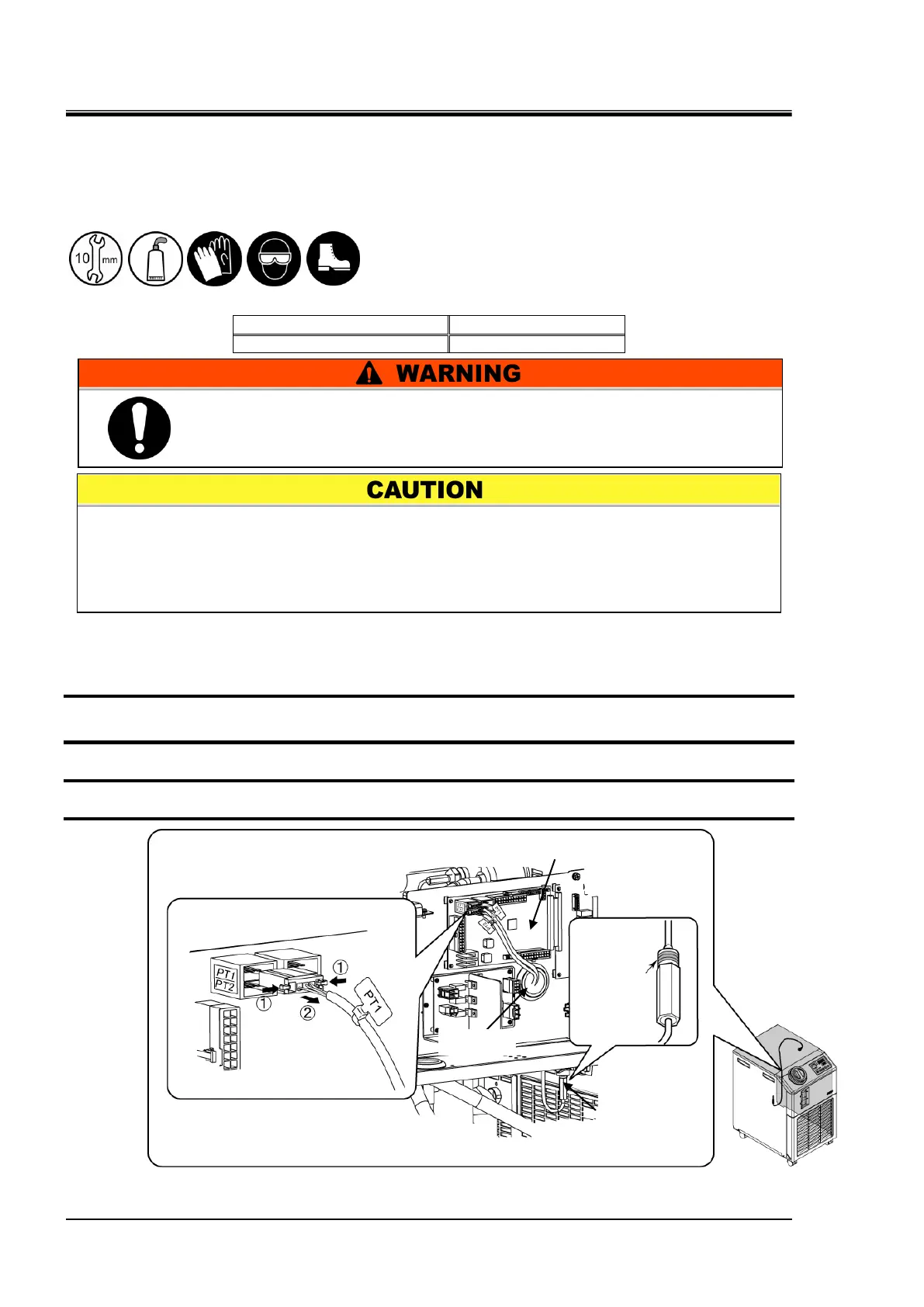
3. Remove the connector (PT1) from the main board.
4. Remove the temperature sensor (PT1).
Fig. 4.5-1 Removal of temperature sensor
When the temperature sensor is removed or mounted, it is turned using a
spanner/wrench. At that time, be careful not to twist its cable. Otherwise, it can
break.
The product must not be operated until the liquid gasket is completely hardened.
Otherwise, it can cause fluid leakage.
Apply the
liquid
gasket before
mounting.
Be sure to shut off the breaker of the facility power supply (the user’s
machine power supply) before replacement work.

 Loading...


