HRX-MM-N007
Chapter 3 Alarm Indication and Troubleshooting
HRS Series 3.1 Alarm Display
Chapter 3 Alarm Indication and
Troubleshooting
3.1 Alarm Display
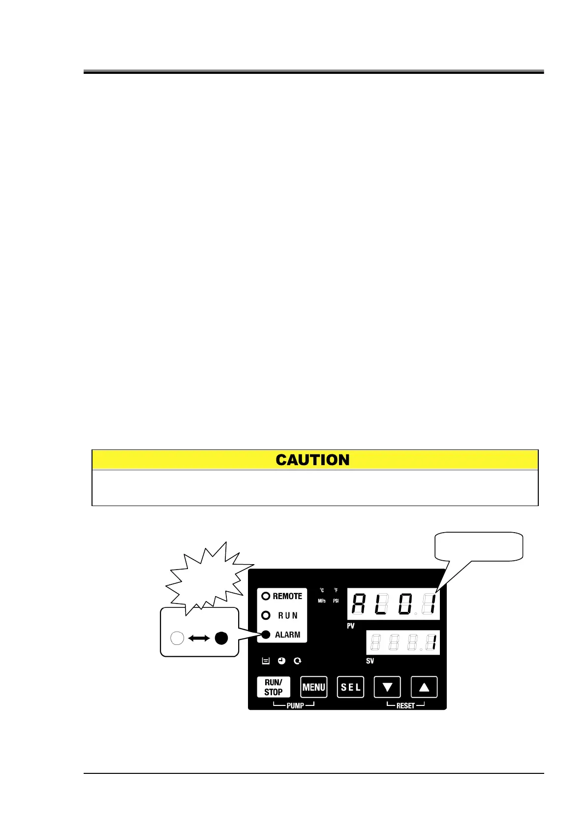
When any alarm occurs, the product responds with the following conditions.
The [ALARM] lamp will flash.
The alarm buzzer sounds.
The alarm no. is displayed on PV.
Contact signal of contact input/output communication is output.
Refer to the Operation Manual for communication for details.
Read alarm status with serial communication.
Refer to the Operation Manual for communication for details.
The thermo-chiller has two types of operation depending on the alarm
status.
One alarm type will stop operation when an alarm is generated during
operation. The other type will not stop operation even when an alarm
is generated.
Only one alarm is displayed on the Thermo-Chiller. When more than
one alarm is being generated, it is possible to check other alarms that
are being generated and not being displayed by pressing the "SEL"
key. When an alarm is being generated, press the "SEL" key to check if
any other alarms are being generated.
Fig.3.1-1 Operation panel
When the alarm is reset, there is a possibility that the alarm display disappears.
Before resetting the alarm, record details of the alarm.

 Loading...


