L
N
HRS***-**-20:200-230VAC 50/60Hz 1Ph
HRS***-**-10:100/100-115VAC 50/60Hz 1Ph
(CN5)
1 3
BK
(CN2)
(CN1)
1 3 5
BK
BK
[G2] Y/G
[G1] Y/G
(CN4)
2
4
(CN3)
1 2
3
BK
BL
BK
RD
[R]
[S]
[C]
1
3
11
22
21
19
10
8
(CN3)
BL
BR
1
2
3
4
BL
BL
BL
BR
[G3][G5]
[G4]
(CN1)
1 2 3 4
5
6 7 8
20
21
6
10
11
16
(CN2)
BL
BL
BR
BL
22
19
BR
BL
(CN2)
1
12
2
13
3
14
1
2
3
4
5
(CN6)
OR
RD
YE
BL
GR
1
2
3
4
5
(CN7)
OR
YE
BL
GR
BK
Y/G
BK
BK
【CM】
【L1】
BK
BK
BL
BL
【L2】
【DCPS】
【CB】
【C2】
【PCB1】
1 3
【PM】
1
【FAN】
「1 Turn」
【L3】
【PCB3】
【PCB4】
4
15
BL
BL
BL
BL
(CN4)
21
8
20
22
11
10
24
23
12
【PS1】
1
2
3
【PS2】
1
2
3
【PS3】
1
2
3
BR
BL
BL
BR
BL
BR
BL
BL
BL
【PCB2】
7
19
BK
BK
【T1】
(CN1)
(CN1)
(CN1)
1
2
3
4
5
6
7
8
9
10
11
12
(TB1)
【L4】
1
2
4
6
7
【L5】
1
2
3
9
5
(CN7)
1A
2A
3A
1B
2B
3B
(CN9)
【PT1】
【PT2】
1
6
(CN4)
~
1
10
(CN5)
~
【EV1】
【EV2】
1. 【 】: Circuit Symbol
2. ( ): Connector No.
3. 「 」: Information
BK
「3Turn」
4. Line color
BK : Black
BL : Blue
BR : Gray
OR : Orange
RD : Red
WH : White
GR : Green
~
【TH】
HRS0-A-
(Air cooling type)
Customer's power supply connection part
WH
BK
「HRS0**-**-20」
YE : Yellow
「3Turn」
「Digital I/O」
「Serial Communication」
「Inside Device」
「Outside Device」
「3Turn」
RD
WH
WH
RD
WH
WH
Y/G : Yellow/Green
Customer's communication connection part
【C1】
「OptionT」
2
13
RD
RD
【LS】
13
2
RD
BK
【SVAF1】
「OptionT:BK」
【C3】
BL
BL
Y/G
「Circulating Fluid Outlet」
「Refrigerant High Press」
「Refrigerant Low Press」
「OptionJ」
「Heating」
「Cooling」
「Circulated Fluid Outlet」
「Circulated Fluid Return」
「Compressor Suction」
「Autmatic Fluid Filling」
「Circuit Breaker」
「OptionB」
「Earth Leakage Breaker」
「OptionT」
「High-pressure Pump」
RD
*1 Option B
*2 Option J
*3 Option T
Circuit Symbol Part Name Circuit Symbol Part Name
【L1】
AC Inlet With Noise Filter
【CB】
Circuit Breaker
Earth Reakage Breaker*1
【DCPS】
DC24V Power Supply
【L2~5】
Ferrite Core
【PS1~3】
Pressure Sensor
【EV1,2】
Electric Expansion Valve
【PT1,2】
Thermistor Sensor
【T1】
Temperature Sensor
Tank Level Switch
【LS】
Solenoid Valve for Auto Filling
【SVAF1】*2
【PCB1】
Main Board
【PCB2】
Communication Board
AC Power Board
【PCB4】
Display Board
【PM】
Pump
High-Pressure Pump*3
【FAN】
Fan Motor
【CM】
Running Capacitor for FAN
【C1】
Compressor
Running Capacitor for CM
【C2】
Running Capacitor for PM*3
【C3】*3
【PCB3】
「Pump」
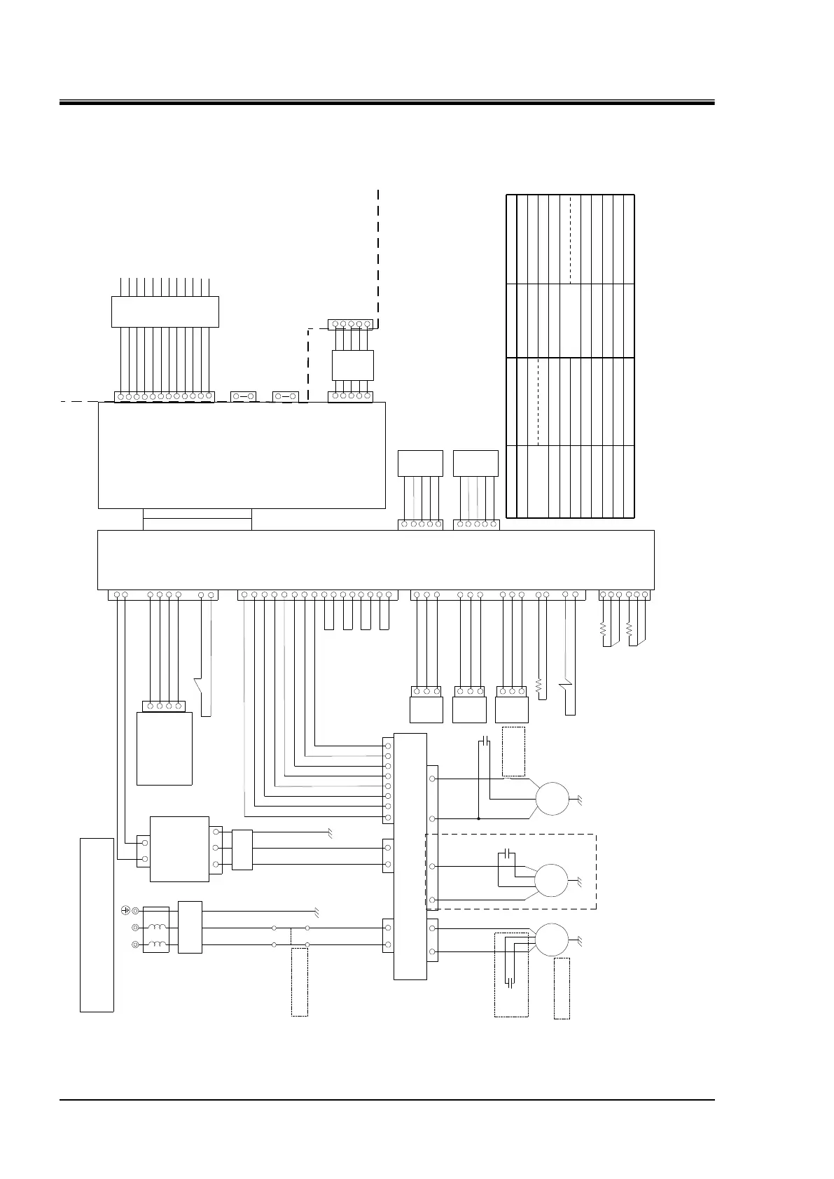
Fig. 6.3-1 Electric Circuit Diagram (HRS0--)
 Loading...


