HRX-MM-N007
Chapter 3 Alarm Indication and Troubleshooting
HRS Series 3.3 Troubleshooting
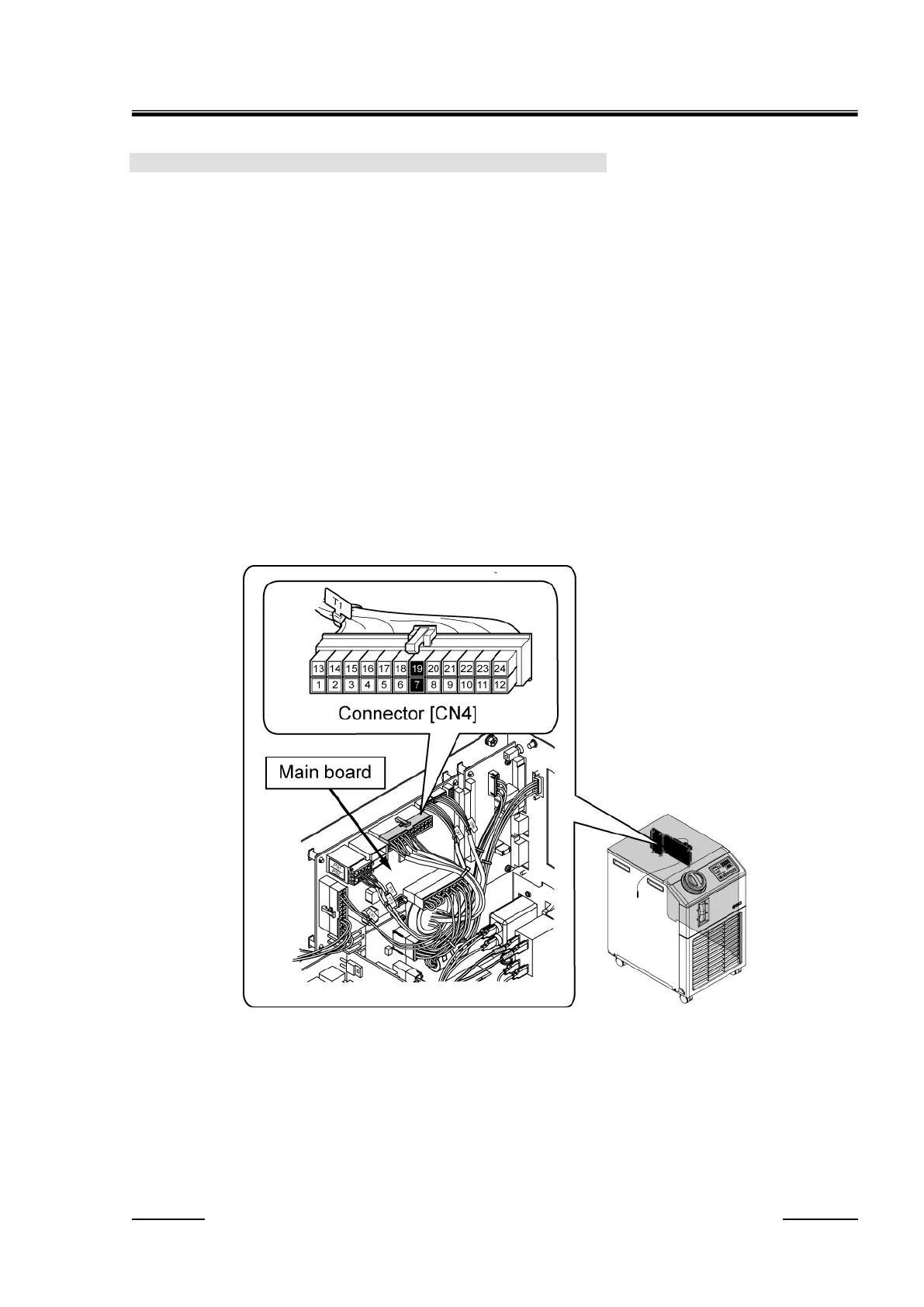
2. Check the compressor intake temperature sensor.
Disconnect the connector "CN4" of the main board. Check the resistance of the pins number 7 to 19
(compressor intake temperature sensor) of the remove cable side connector by following the
instructions shown below:
(1) Leave the Thermo-Chiller not operating for 24 hours. (Make the temperature of the refrigerant
circuit the same as the ambient temperature.)
(2) Measure the ambient temperature.
(3) Disconnect the connector "CN4" of the main board, and measure the resistance between the pin
number 7 and the pin number 19 to which the compressor intake temperature sensor is
connected with a tester.
(4) Check that the resistance and the ambient temperature detected by the tester almost match the
resistances and ambient temperatures shown in Table 3-7 Resistances detected by thermistor
sensor (Reference). If there is a difference of +/- 5
o
C or more in the temperatures, it is judged to
be abnormal.
(AL24 is generated when the temperature reaches -40
o
C or less (resistance: 43.34 kΩ or
more) or 70
o
C or more (0.4895 kΩ or less). When the resistance is 43.34 kΩ or more or
0.4895 kΩ or less, the sensor is judged to have failure.)
Fig. 3.3-73 Check the resistance of the compressor intake temperature sensor
 Loading...


