HRX-MM-N007
Chapter 3 Alarm Indication and Troubleshooting
HRS Series 3.3 Troubleshooting
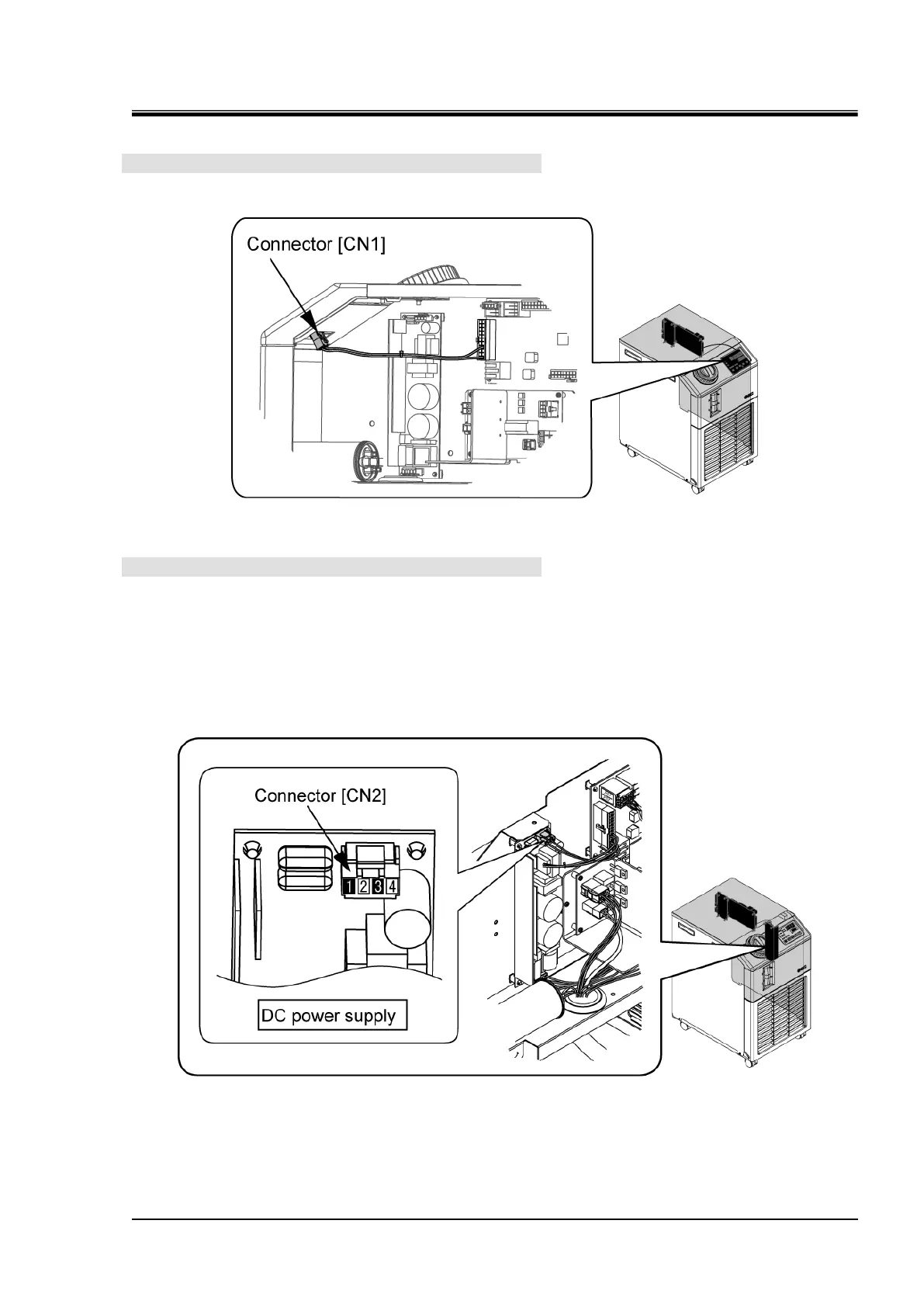
1. Check the connection.
Check that the connector "CN1" of the display board is connected.
2. Check the DC power supply.
Follow the instructions shown below to check that 24 VDC is being output from the DC power supply.
(1) With the DC power supply connector "CN2" connected, directly contact the probe of the tester
with the pins from outside of the connectors.
(2) Contact the negative probe to the pin number 1 and contact the positive probe to the pin number
3 of the "CN2" connector, and measure the DC voltage output.
<Normal> 24 VDC is being output.
Fig. 3.3-77 Check connection of the display board
Fig. 3.3-78 Check the DC power supply output
 Loading...


