HRX-MM-N007
Chapter 4 Service Procedure
HRS Series 4.5 Replacement Procedure
Mounting
1. Mount the inlet socket. (Screw ×2)
Be careful of the mounting direction.
Fig. 4.5-29 Mounting direction in inlet socket
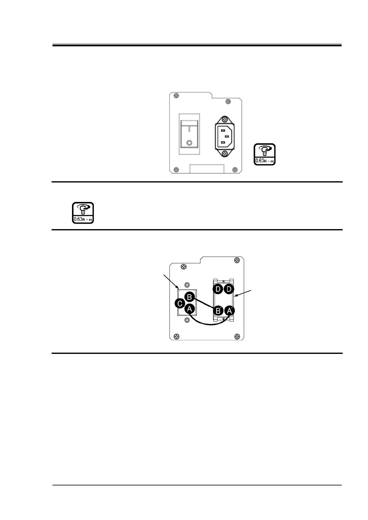
2. Mount the plate. (screw ×4)
3. Insert wiring to terminal A-A’, B-B’, [G1] to terminal C, [LOAD] to terminal D.
Fig. 4.5-30 Entry of connector
4. Mount the upper panel and the side panel on the right in reversed order of removal.
 Loading...


