HRX-MM-N007
Chapter 4 Service Procedure
4.5 Replacement Procedure HRS Series
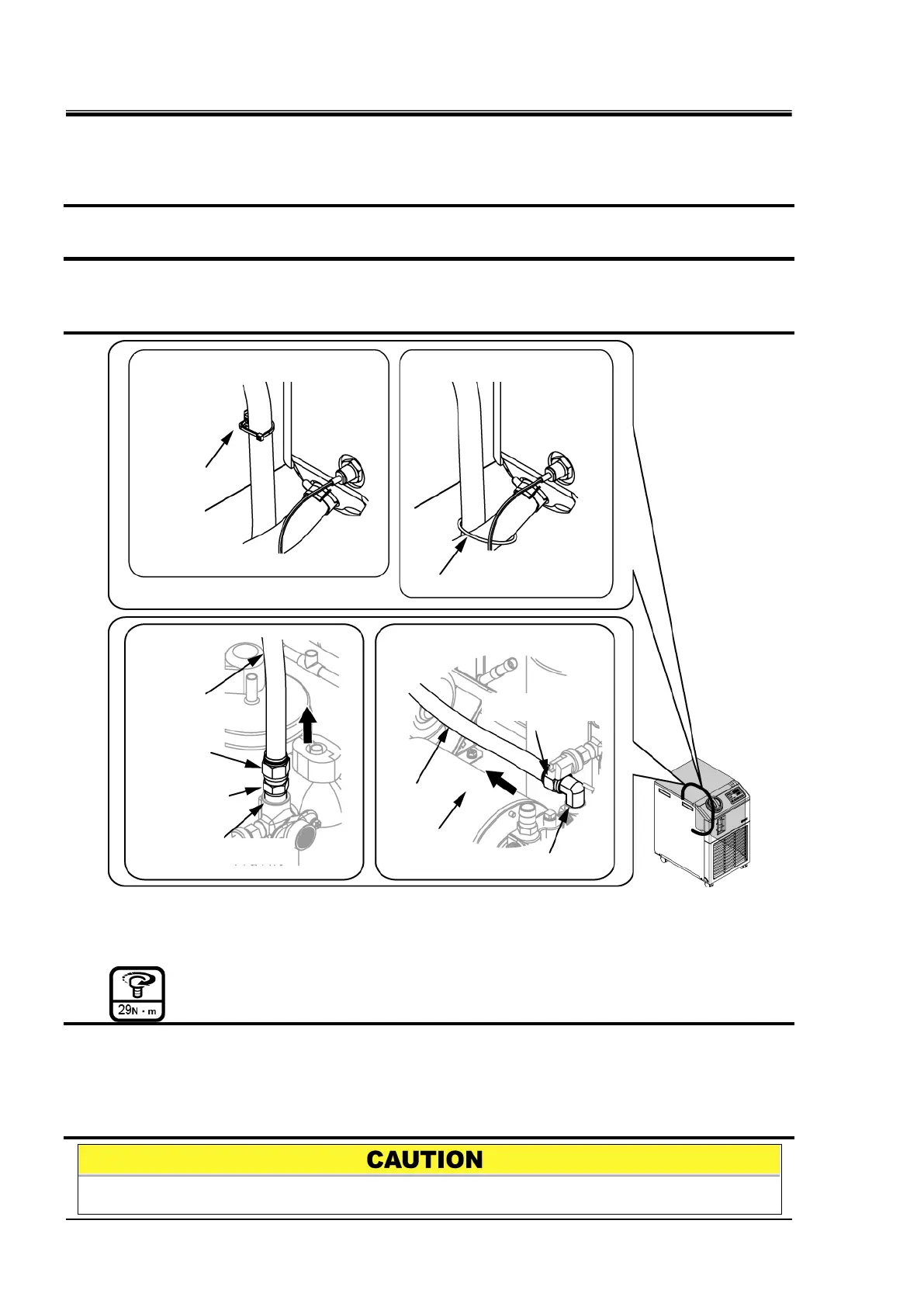
Removal (Between pump- circulating fluid outlet)
1. Discharge the circulating fluid referring the 4.2.2 Discharge of the circulating fluid and
facility water.
2. Remove the upper panel and the side panel on the right referring the 4.2.1 Removal and the
mounting of the panel.
3. The hose fitting is loosened and remove the hose.
For the HRS030-A, cut the cable tie which fixes the hose between the tank and pump.
For the HRS030-W, cut the cable tie fixed on the electrical panel.
Fig. 4.5-45 Removal of plastic hose (Between pump-circulating fluid outlet)
Mounting (Between pump- circulating fluid outlet)
1. Mount the hose fitting to the hose bracket.
2. Mount the upper panel and the side panel on the right in reversed order of removal.
For the HRS030-A, fix the hose between the tank and pump with a cable tie to prevent the hose
between the pump and circulating fluid outlet port from touching the fan motor bracket.
For the HRS030-W, fix the cable tie on the electrical panel.
Check the hose is not twisted after connecting.
 Loading...


