HRX-MM-N007
Chapter 3 Alarm Indication and Troubleshooting
3.3 Troubleshooting HRS Series
1. Check the connection
Securely connect the connectors to
[CN9] of the main board.
Pins of [LS1] must be securely
inserted to the connectors. There
must not be any incorrect insertion
of the pins and defective crimping.
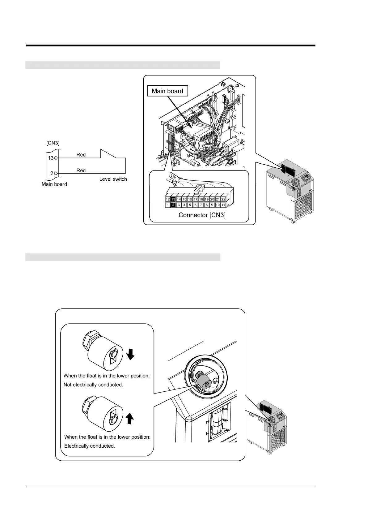
2. Check conditions of the float and contact point
Remove the connectors [CN9]. Move the float of the level switch inside the tank.
Check that it is electrically conducted between the pin numbers 2 and 13 in the state shown below:
- When the float is in the lower position: Not electrically conducted between the contact points 2 and 13.
- When the float is in the upper position: Electrically conducted between the contact points 2 and 13.
Fig. 3.3-3 Level switch connection check
Fig. 3.3-4 Operation of the level switch
 Loading...


