MVC-FD83/FD88
4-7 4-8
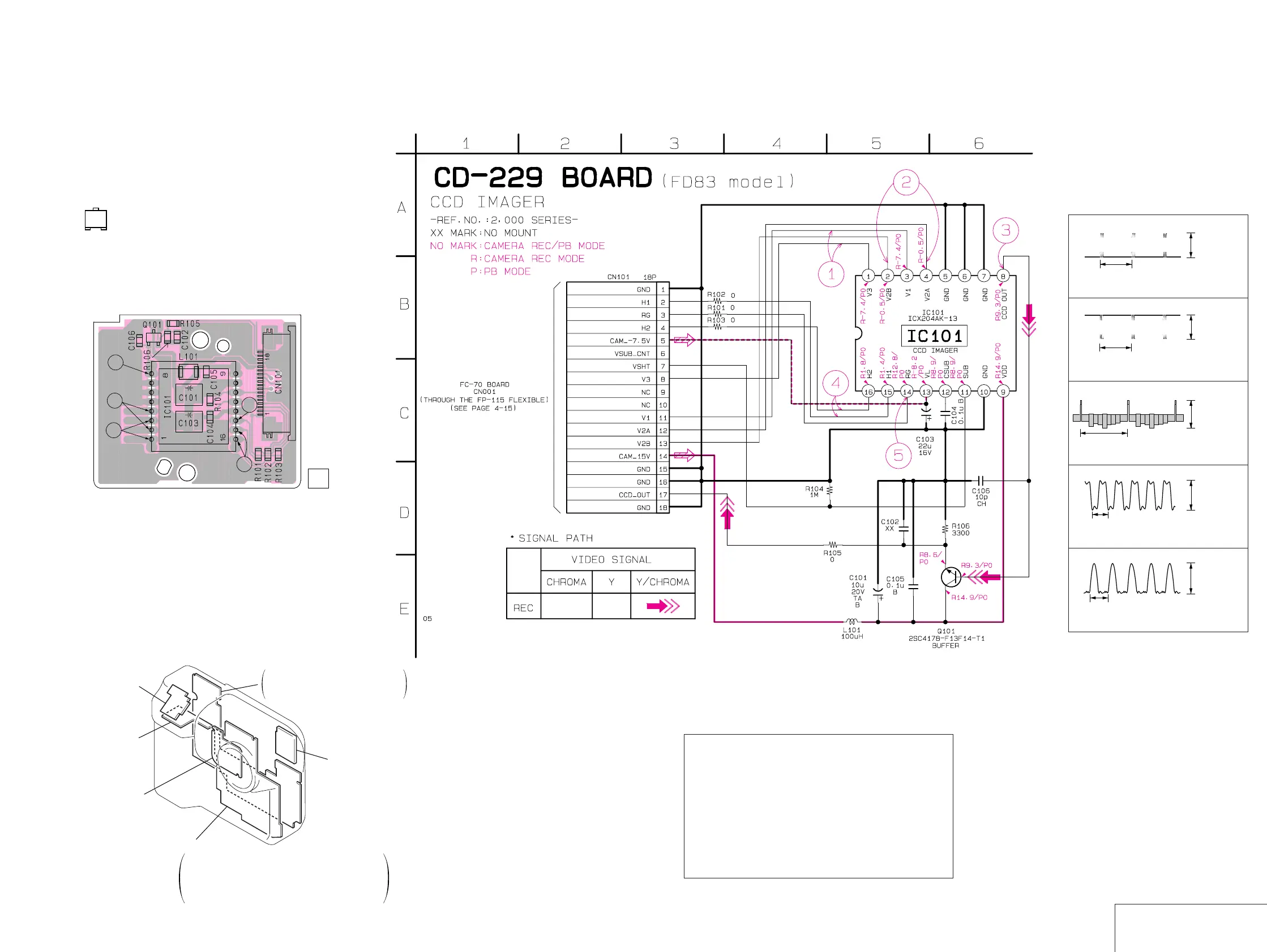
CD-229 (CCD IMAGER) PRINTED WIRING BOARD AND SCHEMATIC DIAGRAM
– Ref. No.: CD-229 board; 2,000 series –
– MVC-FD83 –
• For Printed Wiring Board.
• CD-229 board is 4-layer print board. However, the patterns of
layers 2 to 3 have not been included in the diagram.
• There are few cases that the part isn't mounted in this model
is printed on this diagram.
• Chip transistor
EB
C
Precautions for Replacement of CCD Imager
• The CD-229 board mounted as a repair part is not equipped
with a CCD imager.
When replacing this board, remove the CCD imager from the
old one and mount it onto the new one.
• If the CCD imager has been replaced, carry out all the
adjustments for the camera section.
• As the CCD imager may be damaged by static electricity from
its structure, handle it carefully like for the MOS IC.
In addition, ensure that the receiver is not covered with dusts
nor exposed to strong light.
CD-229 BOARD
CCD IMAGER
CD-229
8.4 Vp-p
8.4 Vp-p
1.7 Vp-p
4.0 Vp-p
4.2 Vp-p
125 µsec
125 µsec
125 µsec
83 nsec
83 nsec
1
2
3
4
5
IC101 1, 3 REC
IC101 2, 4 REC
IC101 8 REC
IC101 !∞, !§ REC
IC101 !¢ REC
05
1-674-160-
11
CD-229
BOARD
3
2
1
4
5
RL-54 (FD83)
RL-56 (FD88)
(RELEASE SWITCH)
PK-47 (FD83)
PK-48 (FD88)
REC/PB AMP, MOTOR DRIVE,
LCD DRIVE, TIMING GENERATOR,
MODE SWITCH, BACK LIGHT DRIVE
FU-135 (FD83)
FU-137 (FD88)
(DC IN)
CD-228 (FD88)
CD-229 (FD83)
(CCD IMAGER)
Flush Unit
FC-70
CAMERA SIGNAL PROCESS, CAMERA DSP,
VIDEO DECODER, LENS MOTOR DRIVE,
AUDIO INTERFACE, MEDIA CONTROL, FD CONTROL,
A/V OUT, AUDIO A/D D/A CONVERTER,
DC/DC CONVERTER