Inter-integrated circuit (I2C) interface UM0306
356/519
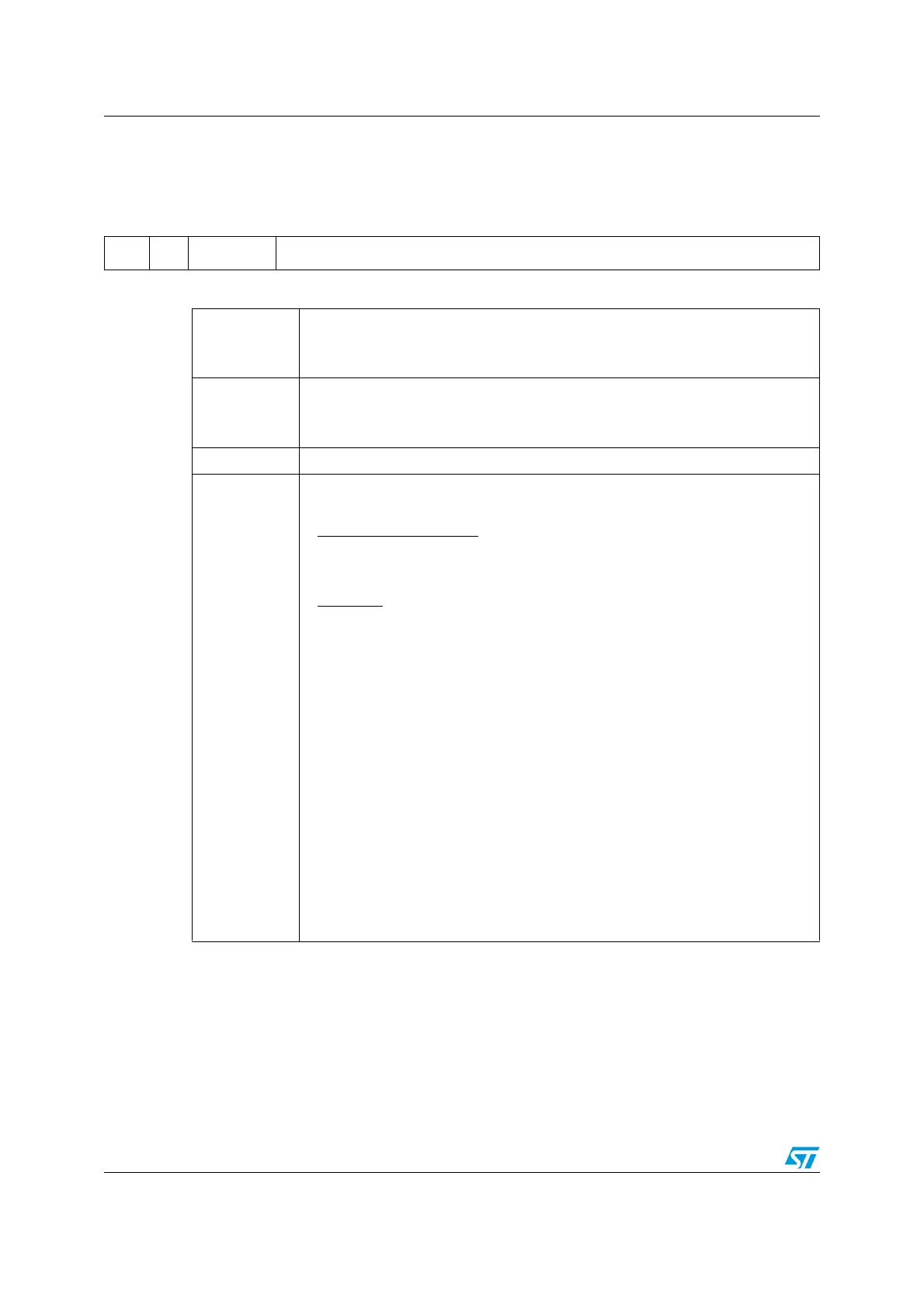
15.6.8 Clock control register (I2C_CCR)
Address offset: 1Ch
Reset Value: 0000h
151413121110987 654321 0
F/S DUTY Reserved CCR[11:0]
rw rw rw rw rw rw rw rw rw rw rw rw rw rw
Bit 15
F/S I
2
C Master Mode Selection
0: Standard Mode I2C
1: Fast Mode I2C
Bit 14
DUTY Fast Mode Duty Cycle
0: Fast Mode t
low
/t
high
= 2
1: Fast Mode t
low
/t
high
= 16/9 (see CCR)
Bits 13:12 Reserved, forced by hardware to 0.
Bits 11:0
CCR[11:0] Clock Control Register in Fast/Standard mode (Master mode)
Controls the SCL clock in master mode.
Standard Mode or SMBus
:
T
high
= CCR * T
CK
T
ow
= CCR * T
CK
Fast Mode:
If DUTY = 0:
T
high
= CCR * T
CK
T
ow
= 2 * CCR * T
CK
If DUTY = 1: (to reach 400 kHz)
T
high
= 9 * CCR * T
CK
T
ow
= 16 * CCR * T
CK
For instance: in standard mode, to generate a 100kHz SCL frequency:
If FREQR = 08, T
ck
= 125ns so CCR must be programmed with 28h
(28h <=> 40d x 125ns = 5000 ns.)
Notes:
1. The minimum allowed value is 04h, except in FAST DUTY mode where the
minimum allowed value is 01h
2. t
high
includes the SCLH rising edge
3. t
low
includes the SCLH falling edge
4. These timings are without filters.

 Loading...


