7-9
764333-098
5. Press UP arrow to select Analog, then press on OK/
NEXT button. Display shows:
Cal analog Ch 1
6. Press OK/NEXT button. Display shows:
1 : Adj 4mA=10329
*
* this value is just an example.
NOTE: If loop calibrator does not show 4 ma, on
Thornton controller press UP, DOWN, RIGHT or
LEFT arrows until signal in loop calibrator displays
4 ma.
On washer control panel:
7. Press CONDUCTIVITY SENSOR touch pad. Dis-
play shows Low point screen.
8. Press START touch pad. Display shows Low Point
Adjustment screen.
9. In Low Point Adjustment screen, press CHANGE
VALUES touch pad. A numeric keyboard appears.
10.Enter 100 on numeric keyboard and press ENTER
touch pad. Display shows High Point screen.
On Thornton controller:
11.Press OK/NEXT button. Display shows:
1 : Adj 20mA= 52708
*
* this value is just an example.
NOTE: If loop calibrator does not show 20 ma, on
Thornton controller press UP, DOWN, RIGHT or
LEFT arrows until signal in loop calibrator displays
20 ma.
On washer control panel:
12.In High Point screen, press START touch pad.
Display shows High Point Adjustment screen.
13.In High Point Adjustment screen, press CHANGE
VALUES touch pad. A numeric keyboard appears.
14.Enter 40000 on numeric keyboard. Press ENTER
touch pad.
15.Summary of Values screen appears; then press OK
touch pad to end conductivity calibration signal.
On Thornton controller:
16.Press OK/NEXT button, display shows:
Save Changes Y
es
17.Press OK/NEXT button to end channel conductiv-
ity calibration.
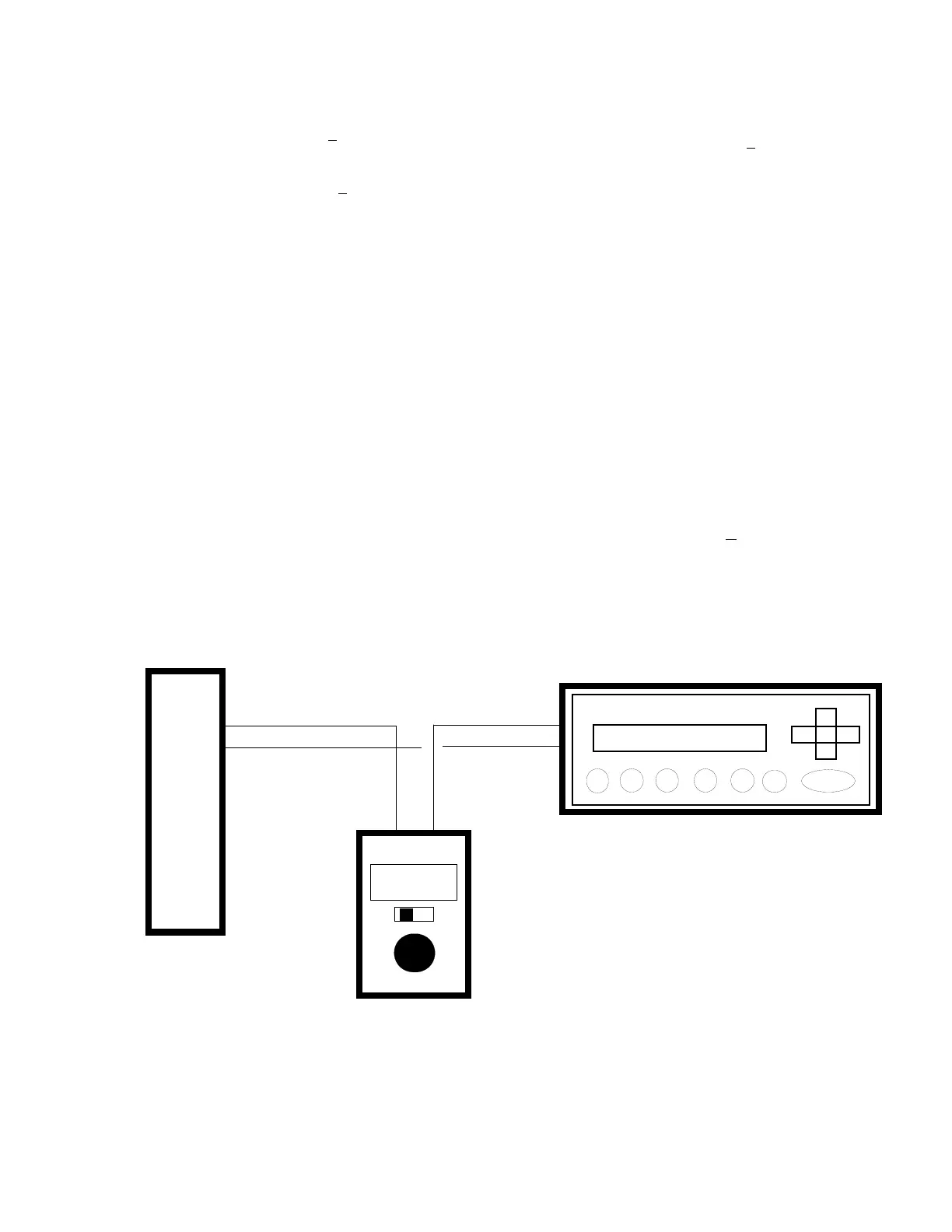
Figure 7-10. Install Loop Calibrator (Channel A)
4-20 ma
Analog Input Module
Slot 3, In1+
Thornton 2000
Loop Calibrator
AO1+
AO1-
[+]
[-]
[+]
[-]




 To Next Page