32 72-1048E MM FL23SE REV A www.stryker.com
Return To Table of Contents
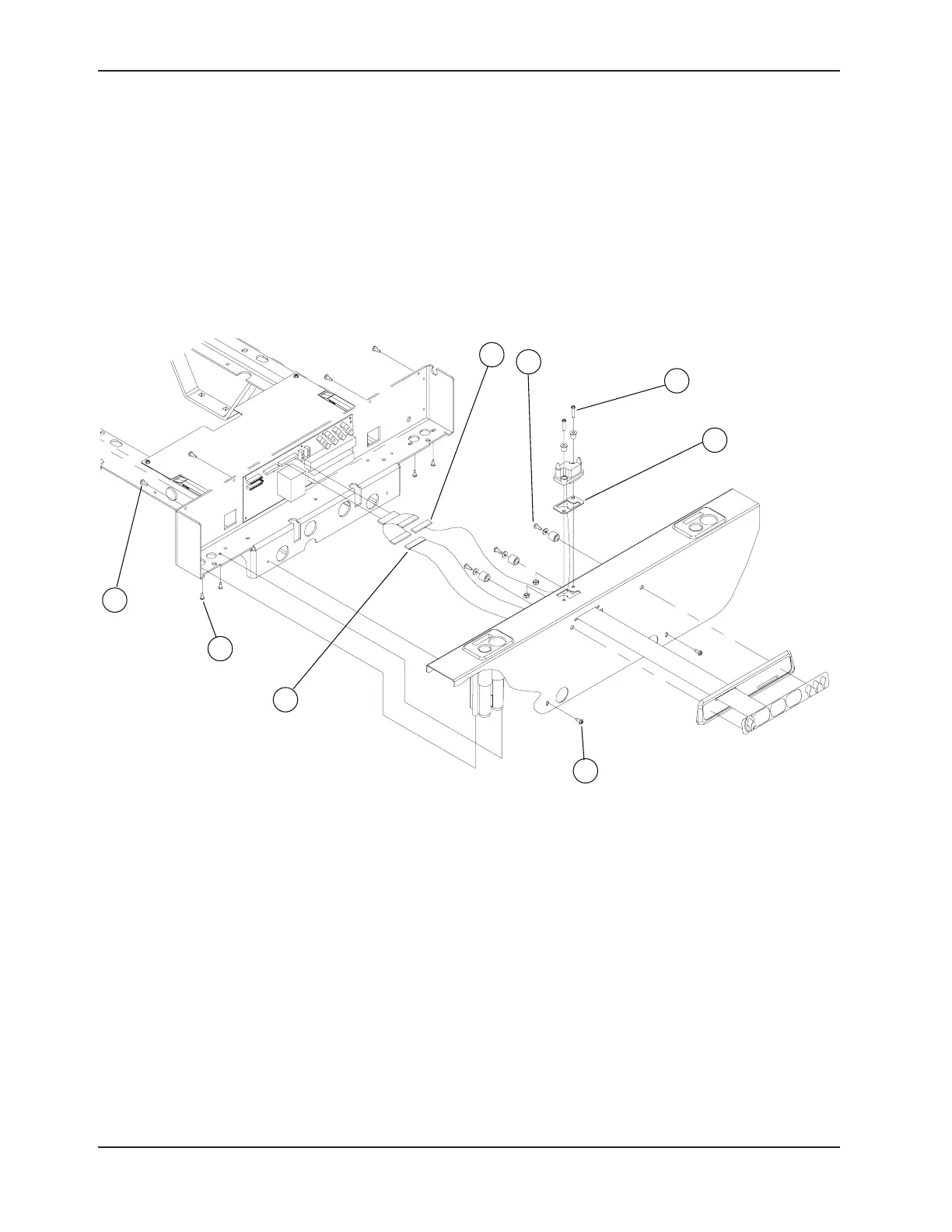
FOOT END CONTROL PANEL REPLACEMENT
Tools Required:
No. 2 Phillips Screwdriver •
Note
The control panel is made of a membrane and its support. Both parts should be ordered for this replacement procedure.
Refer to the “Quick Reference Replacement Parts List” section on pg. 17.
Procedure:
Completely raise the bed and apply the brakes. 1.
Unplug the bed power cord from the wall outlet. 2.
Remove the foot board. 3.
Using the No. 2 Phillips screwdriver, remove the 10 screws (A) holding the cover and the I.V. pole holders to the foot 4.
casing.
Use the Static Discharge Precautions procedure (see 5. pg. 19).
Lift and remove the cover taking care to disconnect the electronic board, the cable (B) from the control panel and, 6.
if applicable, the foot casing connector cable ((optional), C). Lay the cover on a workbench.
Using the No. 2 Phillips screwdriver, remove the three screws, washers and spacers (D) holding the panel to the 7.
cover.
Reverse the above steps to install the new control panel. 8.
Verify all the controls of the foot end control panel before returning the bed to service.9.
Figure 4.2 A
Service Information