www.stryker.com 72-1048E MM FL23SE REV A 47
Return To Table of Contents
BED LIFT MOTOR REPLACEMENT
Tools Required:
1/4” Drive Ratchet•
KR0121 Tool Kit •
Diagonal Pliers •
5/16” Socket •
Small Regular Head Screwdriver •
No. 2 Phillips Screwdriver •
1/2” Combination Wrench•
Bungee Cord •
Procedure:
Note
In order to preserve the adjustment of the bed’s lowest position when replacing a bed lift motor, a special tool kit
designed for that purpose must be used. The kit includes alignment jigs. To obtain this kit, contact our Customer Support
department and order part number KR0121.
Unless otherwise indicated, refer to Figure 4.3 C on pg. 43 for the following replacement procedure.
Position the mattress support sections depending on the location of the bed lift motor to replace: 1.
At the A. foot of the bed: Completely raise the thigh section, then lift and fold back the foot section toward the
head end of the bed. Attach it securely to the bed using
a bungee cord. Finally completely raise the Fowler.
At the B. head of the bed: Completely raise the Fowler.
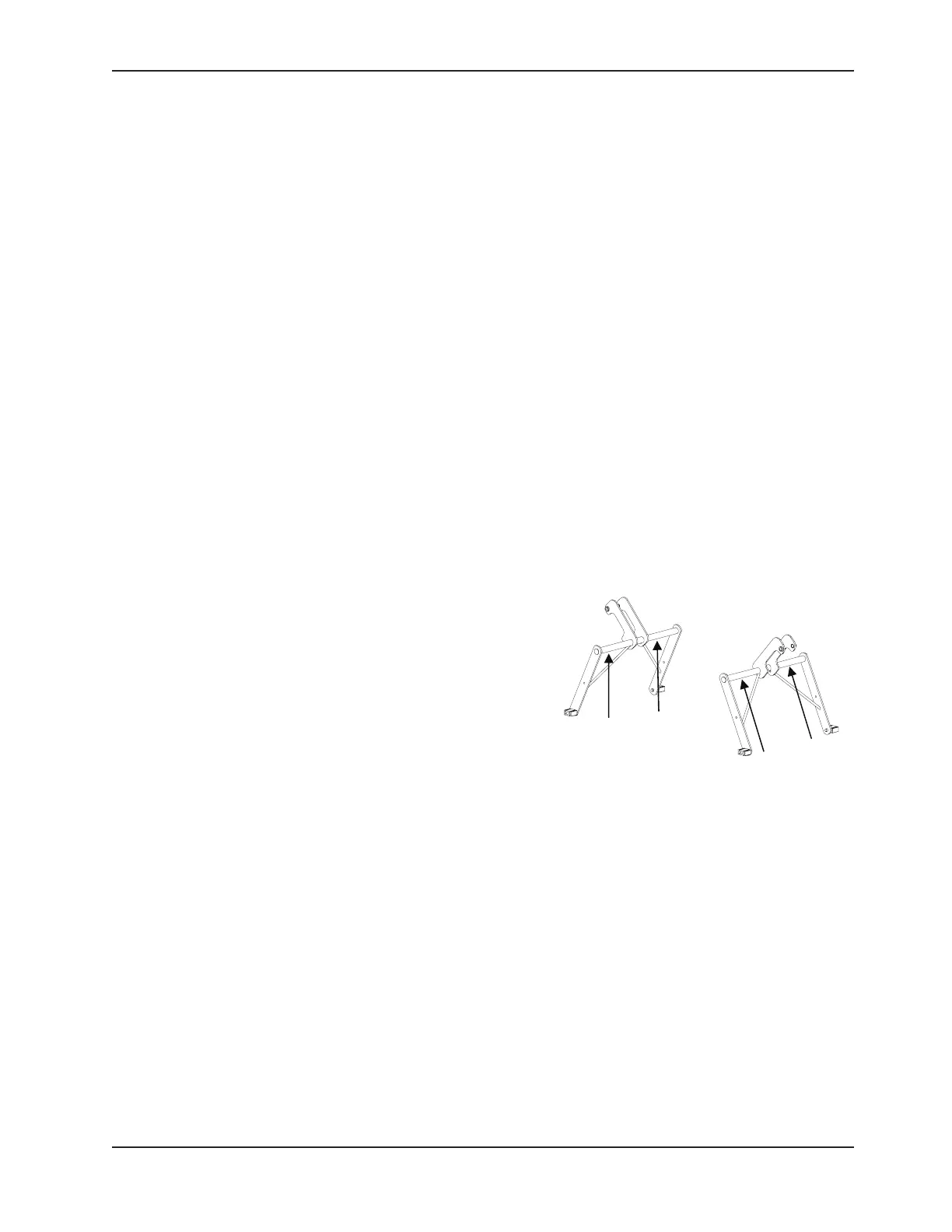
Position the alignment jigs on the floor, on a plane surface, 2.
right under the two transversal tubes supporting the link arms
of both bed lift levers. Lower the bed until the tubes come to
rest on the jigs (see opposite Figure). Use the 3/8” ratchet
wrench with the 1/2” socket provided in the kit to lower a
defective bed lift motor until the tube rests on the jig.
Unplug the bed power cord from the wall outlet. 3.
Raise the siderails. 4.
Disconnect the motor cable and cut, using diagonal pliers, 5.
the cable ties holding it to the frame.
Using the 5/16” socket, remove the two screws (H) holding 6.
the retaining plate to the actuator support.
Remove the two pivot pins (I) holding the motor to the support. To facilitate the removal of the pins, insert the small 7.
regular head screwdriver into the opening at the end of the actuator and push out the pins.
Using the 1/2” combination wrench, remove the two bolts and washers (J) holding the molded nut support to the 8.
Hi-Lo lever. Remove the molded nut support and keep it for the replacement actuator.
Note
Make sure that the support and the molded nut holes are aligned before screwing in the bolts. If resistance is felt, it
means that the holes are not aligned.
Remove the defective motor. 9.
Using the No. 2 Phillips screwdriver, remove the two screws holding together the two parts of the screw cover 10.
(optional) and keep it for the replacement actuator.
Reverse the above steps to install the replacement actuator. Take note of the following caution before hooking up 11.
the motor to the bed lift lever.
Service Information