42 72-1048E MM FL23SE REV A www.stryker.com
Return To Table of Contents
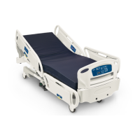
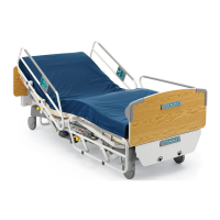
HEAD SECTION REPLACEMENT (CONTINUED)
Using two 1/2” combination wrenches, remove the locknut, spacer and bolt holding the upper part of the compression 7.
bar to the head section and lay it down.
Using two 1/2” combination wrenches, remove the locknut, shoulder spacers and bolt (B) linking the mattress 8.
support lever to the head section and remove the lever-compression bar assembly.
Remove the strap and manually lower the head section completely. 9.
If the bed is equipped with half-length siderails, lower the head siderails and use the No. 2 Phillips screwdriver 10.
to remove the four screws (K, Figure 4.1 A, pg. 22) holding the two siderail supports to the head section. Let the
support-siderail assembly rest on the frame.
Using the 1/2” combination wrench, remove the two locknuts, flat washers, shoulder spacers and bolts (G) linking 11.
the head section to the seat section. Remove the defective head section.
Using the no. 2 Phillips screwdriver, remove the two screws (J) holding the micro switch activator (optional) to the 12.
head section.
Note
This activator is present only if the bed is equipped with the optional Auto Contour positioning. Remember the position of
the micro switch activator before removing the screws. Properly positioned, the blade of the Auto Contour micro switch
is pushed in by the activator when the Fowler is in flat position.
Reverse the above steps to install the replacement head section. 13.
Verify the Auto Contour positioning (optional) for proper operation before returning the bed to service. 14.
End of the procedure for beds with Auto Contour.
Note
Unless otherwise indicated, refer to Figure 4.3 A on pg. 37 for the following replacement procedure.
Disconnect the two wires (A, Figure 4.3 F, 15. pg. 54) from the micro switch located on the head section lever. Note
their position before doing so.
Using two 7/16” combination wrenches, remove the locknut and bolt (O, Figure 4.3 F, 16. pg. 54) holding the cylinder
end fitting to the head section.
Using two 1/2” combination wrenches, remove the nut, shoulder spacers and bolt (P, Figure 4.3 F, 17. pg. 54) holding
the upper part of the section lever to the head section.
Using a 7/16” combination wrench, remove the two locknuts and bolts (Q, Figure 4.3 F, 18. pg. 54) holding each CPR
release handle to the head section.
Remove the strap and manually lower the head section completely. 19.
If the bed is equipped with half-length siderails, lower the head siderails and use the No. 2 Phillips screwdriver 20.
to remove the four screws (K, Figure 4.1 A, pg. 22) holding the two siderail supports to the head section. Let the
supports-siderails assembly rests on the frame.
Using the 1/2” combination wrench, remove the two locknuts, shoulder spacers, washers and bolts (G) holding the 21.
head section to the seat section. Remove the defective head section.
Using the No. 2 Phillips screwdriver, remove the two screws holding the activator (J) to the head section.22.
Note
Note the position of the activator before removing the screws. Properly positioned, the blade of the CPR and Auto
Contour (optional) micro switches are pushed in by the activator when the Fowler is in flat position.
Reverse the above steps to install the replacement head section. 23.
Verify the CPR emergency release and the Auto Contour positioning (optional) for proper operation before returning 24.
the bed to service.
End of the procedure for beds with CPR and Auto Contour.
Service Information
 Loading...