S CLASS™ cutter User’s Manual
Contour Cutting 3-6
1
2
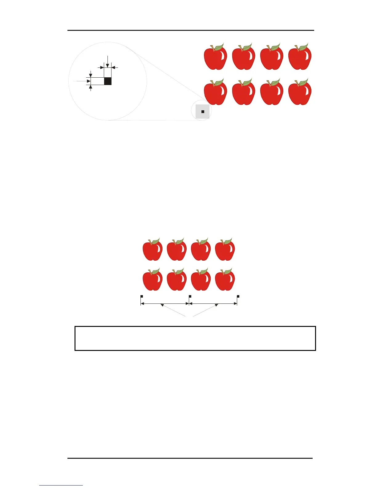
4. Set the line style of the marker to None. Line styles of varying thickness can alter
the size of the markers. Make sure there is a white margin of about 3 to 4 times
the marker size around the marker (in the above picture this area is represented
by a gray area). If anything is printed within this margin, the sensor may be unable
to locate the marker.
5. Make sure that the Origin marker is situated below and to the left of all contours to
be cut.
6. Insert horizontally aligned copies of the Origin marker at regular intervals (X-
Distance). Together, these markers indicate the X-Axis.
The X-Distance (1) is the distance from the lower left corner of one marker to the
lower left corner of the next marker and depends on several factors. The X-Distance
must be known when setting the OPOS parameters manually.
1
NOTE: OPOS will operate faster as the X-Distance increases. Conversely, OPOS
will operate more accurately as the X-Distance decreases; however, the impact on
accuracy is minimal. Recommended distance between the markers is 400mm.
7. Make sure there is enough white space around each marker. The X-Distance
should be increased if the margin of white space around the marker is not 3 to 4
times larger than the marker itself.
8. Make sure that the markers are perfectly level with one another.
9. Make a copy of the row of markers created in step 5. Place this new row above the
graphic to indicate the Y-Axis.