128 Sun StorageTek 2500 Series Array Hardware Installation Guide • September 2009
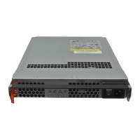
FIGURE E-1 Power Fan Assembly Locations.
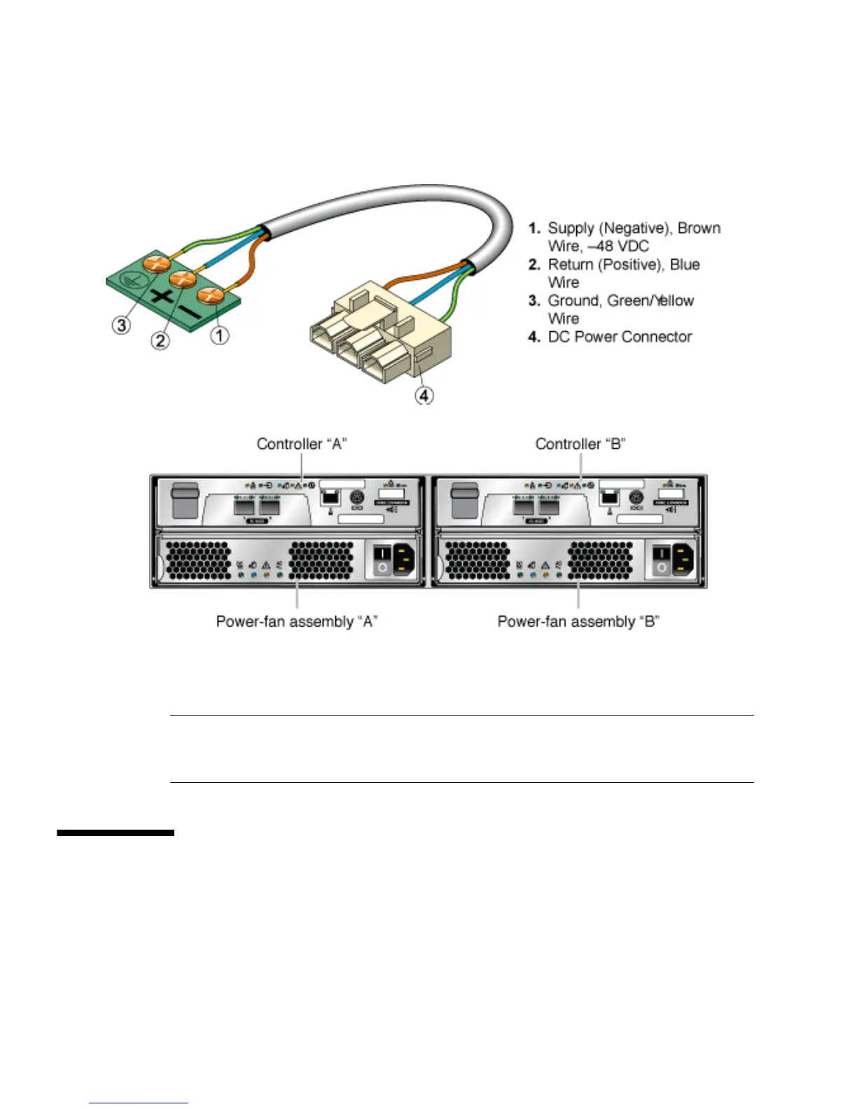
FIGURE E-2 DC Power Connector Cable and Source Wires
The power-fan assemblies above are shown with AC power connectors. The DC
power connector can be seen in
FIGURE E-3.
Caution – Risk of electrical shock – The tray has more than one power source.
To remove all power from the tray, all DC MAINS must be disconnected by removing
all power connectors (item 4 in Appendix E) from the power-fan assemblies.
Installation Notes for DC Power
The sections that follow provide hardware information about DC power.
■ “Ship Kit Changes” on page 129
■ “DC Power LEDS” on page 129