16 Sun StorageTek 2500 Series Array Hardware Installation Guide • September 2009
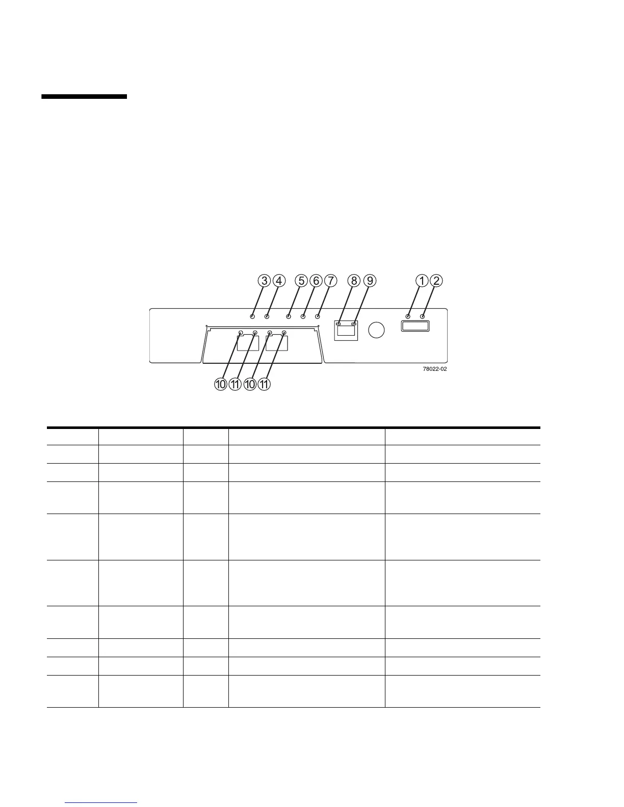
LEDs on the Rear of the Trays
Controller LEDs on the Sun StorageTek 2540 and
Sun StorageTek 2510 Arrays
FIGURE 1-11 Locations of the Controller LEDs on the Sun StorageTek 2540 and 2510 Arrays
TABLE 1-3 Descriptions of the Controller LEDs on the 2540 and 2510 Arrays
Location LED Color On Off
1 Link Fault Amber At least one link has an error. Normal condition
2 Drive Link Green At least one link is active. At least one link has an error
3 Battery Fault Amber Indicates a fault within the
battery backup unit.
Normal condition
4 Cache Active Green Steady green indicates that data
is in the cache.
Indicates that all data has been
written to the disk and the cache
is empty.
5 Service Action
Allowed
Blue The controller can be removed
from the controller tray.
The controller cannot be
removed from the controller
tray.
6 Service Action
Required (Fault)
Amber Indicates a fault within the
controller.
Normal condition
7 Power Green Tray is powered on. Tray is not powered on.
8 Ethernet Link Green The connection is active. The connection is not active.
9 Ethernet
100BASE-TX
Green 100BASE-TX connection is
active.
The 100BASE-TX connection is
not active.