Appendix E Using DC Power 129
■ “Connecting Power Cables” on page 130
■ “Turning Off the DC Power During an Emergency” on page 131
■ “Relocation Cautions” on page 131
Ship Kit Changes
If the DC power option is ordered, two DC power connector cables are provided with
each controller tray for connection to centralized DC power plant equipment.
Caution – A qualified service person is required to make the DC power connection
per NEC and CEC guidelines. A two-pole 20-amp circuit breaker is required between
the DC power source and the tray for over-current and short-circuit protection.
Before turning off any power switches on a DC-powered CRU or module, you must
disconnect the two-pole 20-amp circuit breaker.
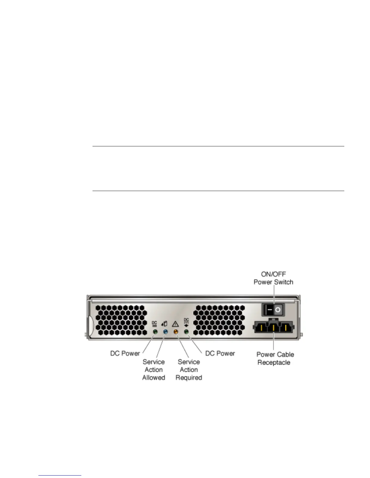
DC Power LEDS
FIGURE E-3 shows the LEDs, on/off power switch, and power cable receptacle on the
back of the DC power-fan assembly.
FIGURE E-3 DC Power-Fan Assembly LEDs, Power Switch, and Power Cable Receptacle.
TABLE E-1 lists the LEDs for DC power.