Chapter 2 Installing Trays 49
To cable a 1x3 array configuration for maximum redundancy:
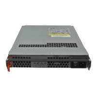
1. Locate the Controller A and Controller B expansion ports at the back of the
controller tray (
FIGURE 2-16).
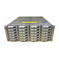
2. Locate In and Out expansion ports at the A-side and B-side back of the
expansion tray (
FIGURE 2-17).
3. Connect one SAS cable between the Controller A expansion port and the A-
side expansion In port of expansion tray 1 (
FIGURE 2-19).
4. Connect one SAS cable between the Controller B expansion Out port and the B-
side expansion In port of expansion tray 2 (
FIGURE 2-19).
5. Connect one SAS cable between the expansion tray 1 Out port and the A-side
expansion In port of expansion tray 2 (
FIGURE 2-19).
6. Connect one SAS cable between the expansion tray 2 B-side Out port and the
B-side In port of expansion tray 1 (
FIGURE 2-19).
Cabling a Third Drive Expansion Tray
Each additional expansion tray is added to the preceding expansion tray by
connecting two additional SAS cables from the Out ports of the preceding tray to the
In ports of the next tray in the loop.
FIGURE 2-20 illustrates a 1x4 storage array
configuration consisting of one controller tray and three expansion trays.
The cable connections on the B-side are reversed (the cable from the controller A
expansion port goes to the In port of expansion tray 1; the cable from the controller
B expansion port goes to the In port on expansion tray 3) for maximum redundancy.