4. Fuel Injection System
4-6
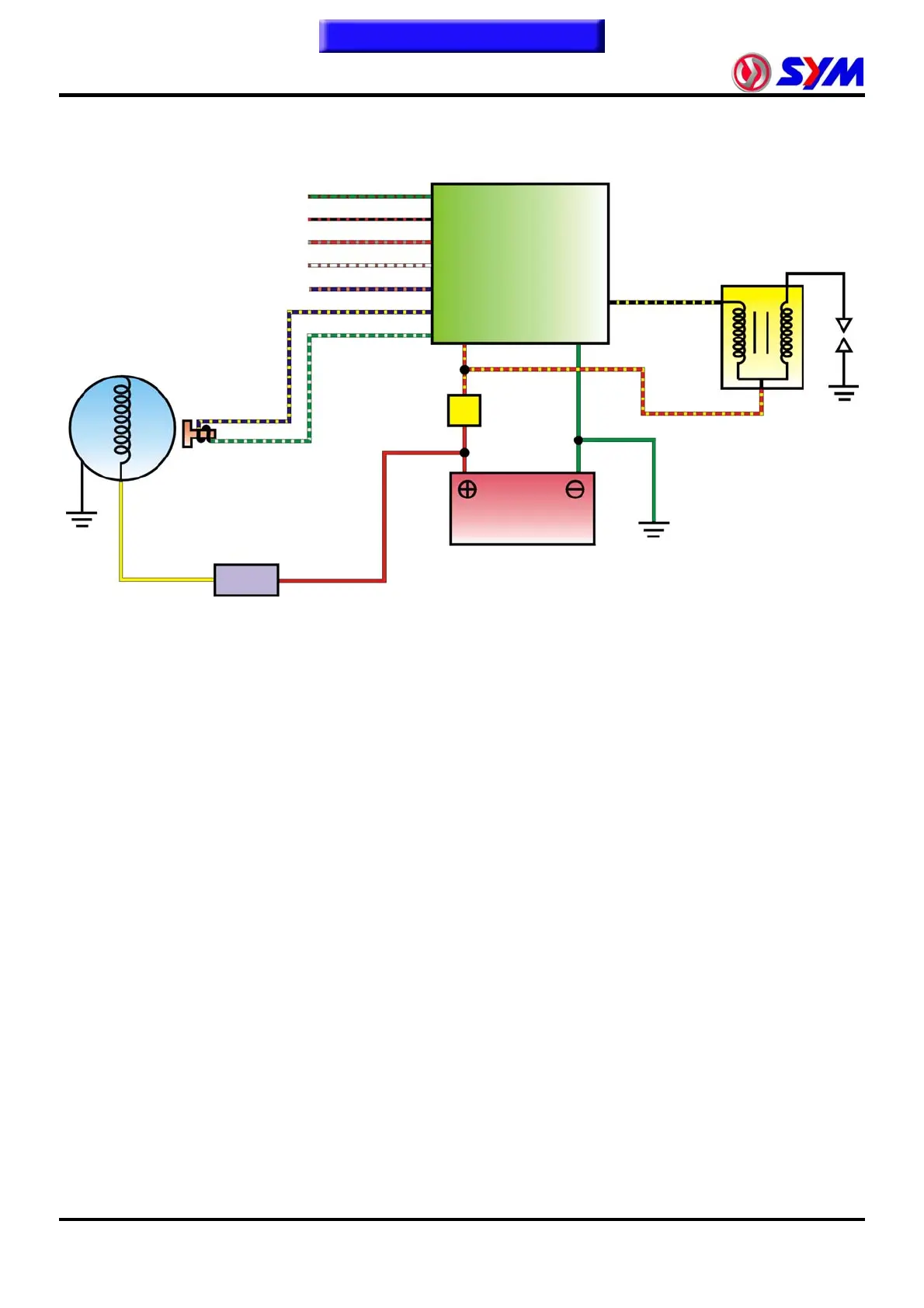
Ignition System
Principle
The computer programmed ignition system receives the signals from the Crankshaft position sensor,
Throttle position sensor, O
2 Sensor, MAP sensor, Intake air temperature sensor, Engine coolant
temperature sensor. Calculating the engine RPM, the 16-bit microcomputer determines the appropriate
ignition timing, controls the ignition coil and triggers the spark plug. This way can not only make the
engine achieve the maximum power output, but also help improve fuel consumption rate.
Specifications
1. Ignition timing: BTDC 10 ° / 1650RPM
2. Spark plug: NGK CR8E Clearance: 0.6 to 0.7 mm
3. ACG crankshaft position sensor coil resistance: 80 ~ 160 Ω (Green / White - Blue / Yellow)
4. Ignition coil primary circuit resistance: 2.8 Ω ± 15% (20 º C) (Red / Yellow - Black / Yellow)
5. Battery Type / Capacity: YTX12A-BS or GTX12A-BS / 12V 12Ah
ACG/ Flywheel Gear
(23+1 Long teeth)
Crankshaft
position
Throttle position
Manifold absolute pressure
Engine coolant temperature
REG. REC.
Ignition coil
Spark plug
ECU
Oxygen content
Battery
Intake ai
temperature
Power relay
To this chapter contents

 Loading...