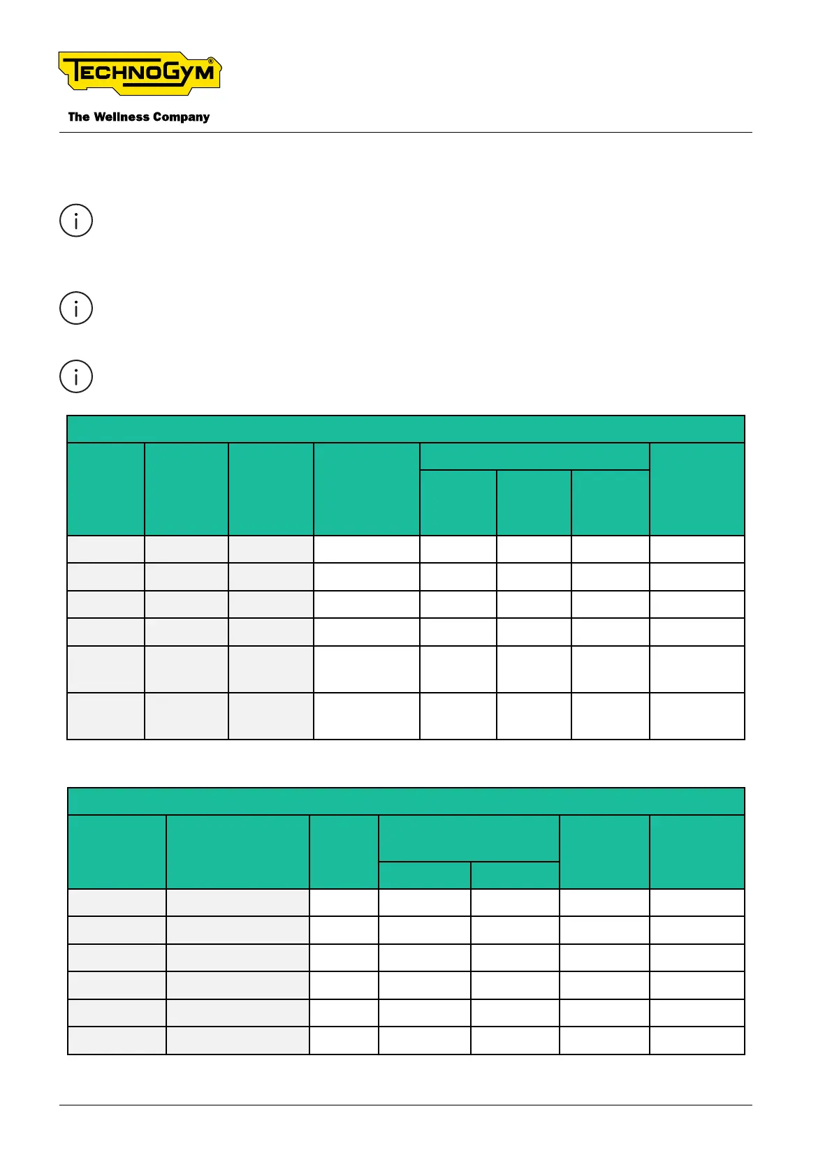
2.11 WIRING DETAIL
The wiring diagrams shown above list the complete cable codes. The string xx indicates the-
generic version.
The colour of the cables may change: in particular, refer to the Pin Out.
Acronyms: GND:Ground; FC: ying connection; CN: connector.
-
ry)
Signal
SCHURTER SWITCH
-
ary)
Line
1 Neutral Light blue Faston
2 - -
3 Phase Brown Faston
4 - -
5 Ground
Yellow/
Green
Ring
Ring Ground
Yellow/
Green
Faston
Tab. 7
Signal
Electromagnetic
Fc to
RPM sen-
sor
GND RPM
sensor
1 Inductive brake + White Faston
2 Inductive brake - Grey Faston
3 RPM Brown Faston
4 GND RPM Black Ring
5 - -
6 - -
Tab. 8
TECHNOGYM ELLIPTICAL Technical Service Guide
Rev. 1.1
- 16 -
Uncontrolled copy if printed Uncontrolled copy if printed