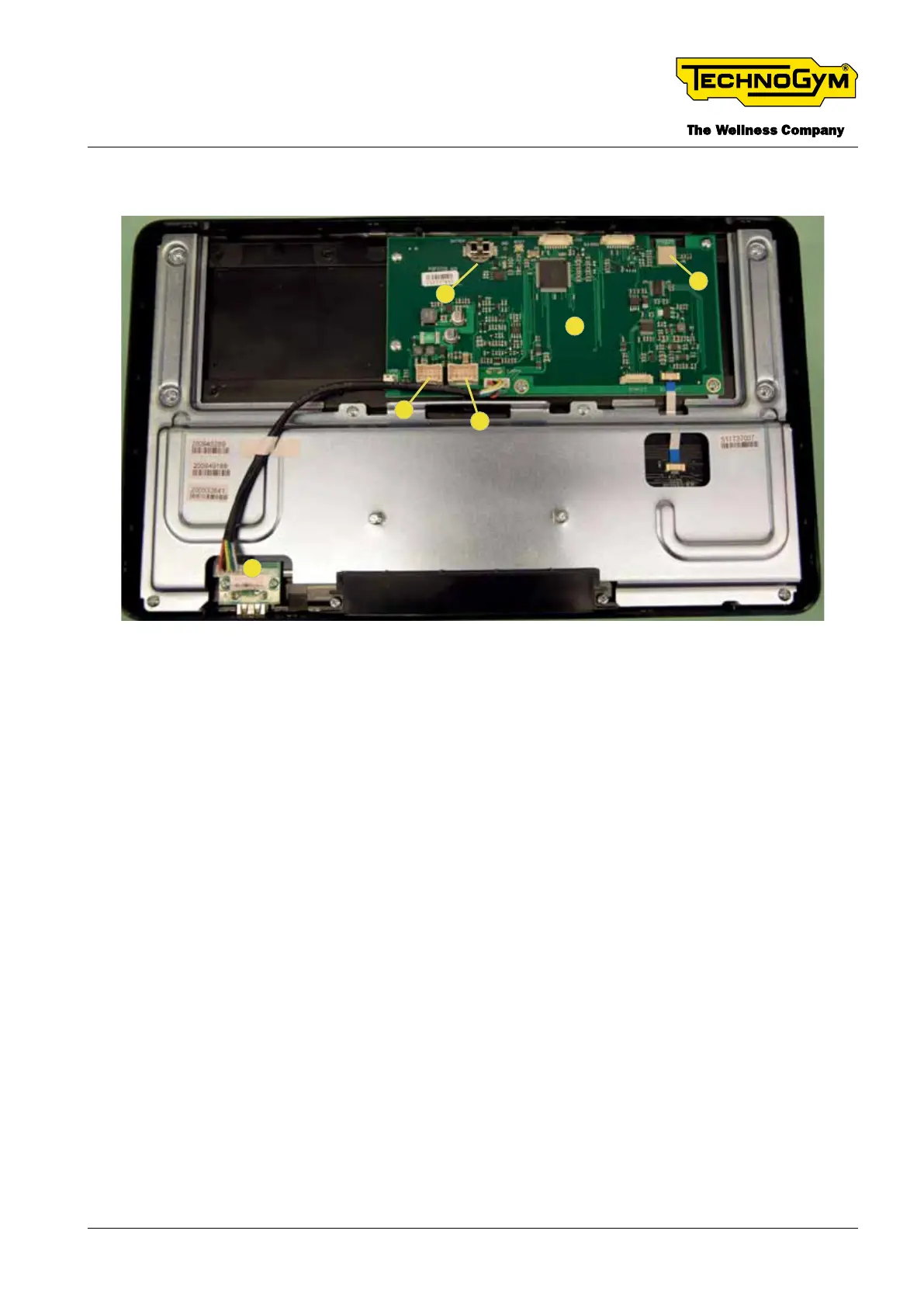
3.7 DISPLAY (LCD)
1
2
3
4
6
5
Fig. 6
[1]: USB Board; [4]: BLE module
[2]: CPU board; [5]: Power connector - digital connection with Low-Kit
[3]: BackUp Battery [6]: Joystick connector
3.7.1 CPU BOARD
The CPU board contains SW identied with a version number.
The main functions of the CPU Board are the management of the following components:
▪ RS-485 serial line to the brake board;
▪ LCD display;
▪ USB port.
After a few seconds of inactivity (e.g. 60 sec), the equipment goes into stand-by mode: the CPU
sends a sleep signal to the low-kit to minimise energy use. During stand by status the following
conditions occurs:
_the display is o;
_the functon of charging a client device battery from the USB port is disabled;
_the BLE module is o.
TECHNOGYM ELLIPTICAL Technical Service Guide
Rev. 1.1
- 23 -
Uncontrolled copy if printed