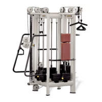
17. Using a 6-mm Allen wrench, back off the
part i and remove all the components shown
in the figure, in the lower right-hand box,
also using a 6-mm pointed tool.
18. Also remove components l and m from the
group on the opposite side.
19. To remove component l, use a 4-mm Allen
wrench to back off the screw and the grub
screw. If necessary, use a flat head
screwdriver to hold open the hole of the
hook, so that it can be removed without
damaging the knurled surface of the barbell.
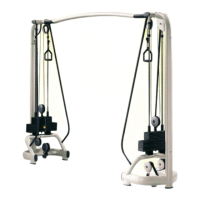
20. Insert the barbell in the sleeve assembly that
slides along the first machine guide rod, as
shown in the figure.
21. Reassemble components l and m on either
side of the barbell and insert the barbell also
into the sleeve assembly on the second guide.
Component "m" must be inserted with
the hollow part on the outside.
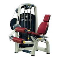
22. Reassemble the various components of the
barbell from the outside, in the same order as
they were removed, as shown in the figure.
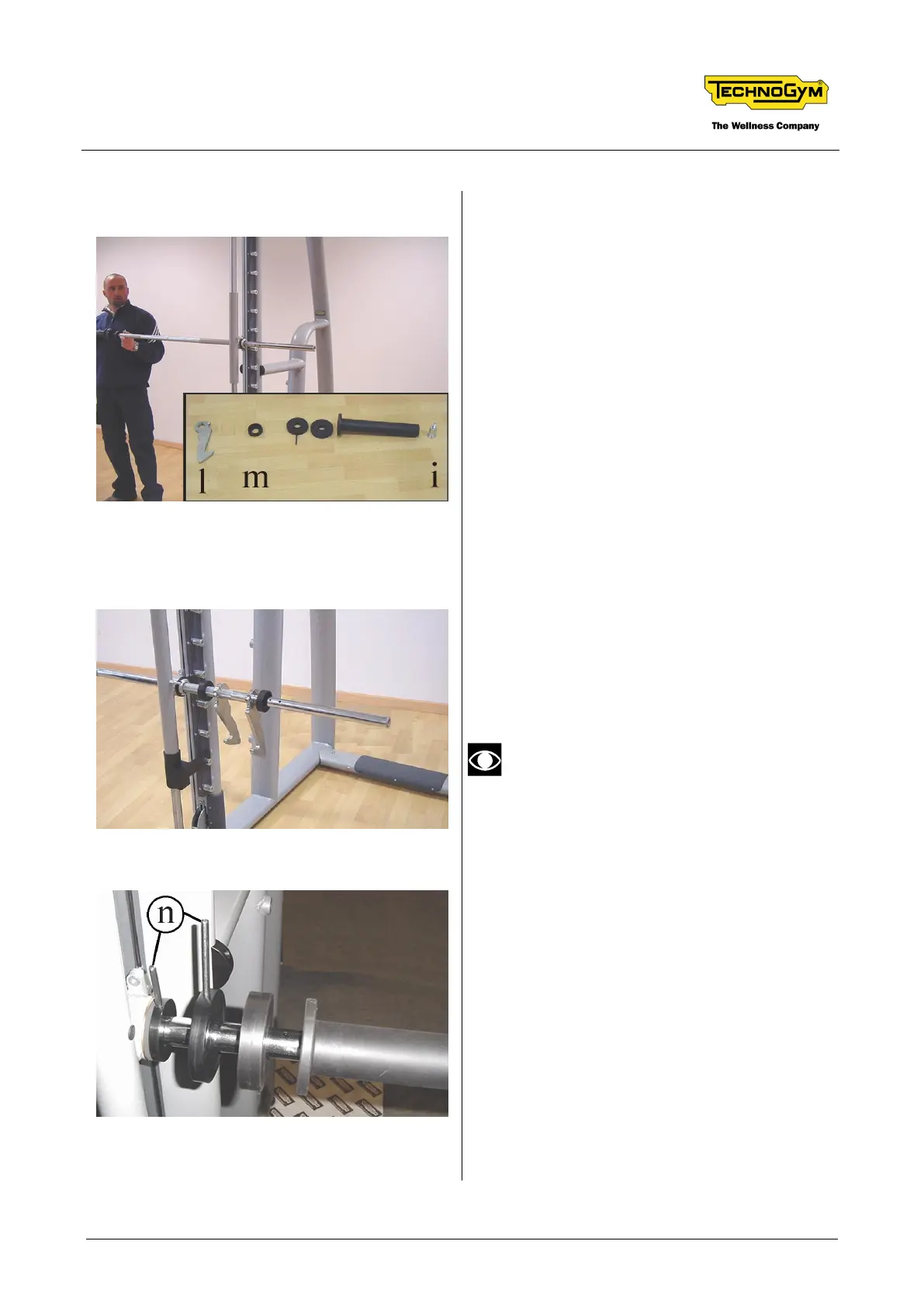
23. Fix the various spacers using the pins n,
supplied together with the machine.