Options and
Accessories-2230
Operators
NOTE
Do not hook
up
external devices to both
the
DTE
connector and
the
DCE connector
at
the
same
time.
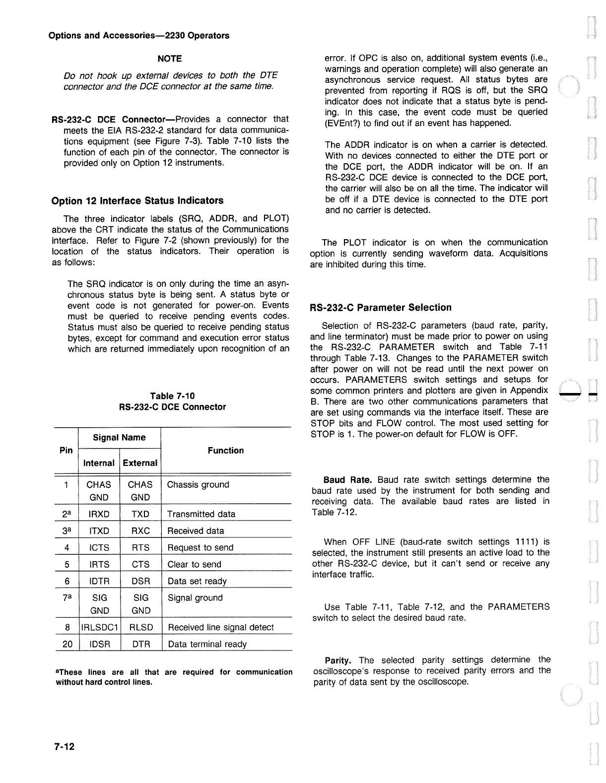
RS-232-C
DCE
Connector-Provides a connector that
meets the EIA RS-232-2 standard for data communica-
tions equipment
(see
Figure
7-3).
Table 7-10 lists the
function of
each
pin
of the connector. The connector
is
provided only
on
Option 12 instruments.
Option 12 Interface Status Indicators
The
three indicator labels (SRQ, ADDR,
and
PLOT)
above the
CRT
indicate the status of the Communications
interface. Refer to Figure
7-2
(shown previously) for the
location of the status indicators. Their operation
is
as follows:
The
SRQ
indicator
is
on
only during the time
an
asyn-
chronous status byte
is
being
sent. A status byte or
event code
is
not generated for power-on. Events
must
be
queried to receive pending events codes.
Status must also
be
queried to receive pending status
bytes, except for command
and
execution error status
which
are
returned immediately upon recognition of
an
Pin
1
2a
3a
4
5
6
7a
8
20
Table 7-10
RS-232-C
DCE
Connector
Signal Name
Function
Internal
External
CHAS
CHAS
Chassis ground
GND
GND
IRXD
TXD
Transmitted data
ITXD
RXC
Received
data
ICTS
RTS
Request to
send
IRTS
CTS
Clear to
send
IDTR
DSR
Data set ready
SIG SIG
Signal ground
GND GND
IRLSDC1
RLSD
Received
line
signal detect
IDSR
DTR
Data terminal ready
8
These lines are
all
that are required for communication
without hard control lines.
7-12
error. If
OPC
is
also
on,
additional system events (i.e.,
warnings
and
operation complete) will also generate
an
asynchronous service request.
All
status bytes are
prevented from reporting if
RQS
is
off, but the SRQ
indicator does not indicate that a status byte
is
pend-
ing.
In
this
case,
the event code must
be
queried
(EVEnt?) to find out if
an
event has happened.
The
ADDR
indicator
is
on
when a carrier
is
detected.
With
no
devices connected to either the
DTE
port or
the
DCE
port, the
ADDR
indicator will
be
on. If
an
RS-232-C
DCE
device
is
connected to the
DCE
port,
the carrier will also
be
on
all
the time.
The
indicator will
be
off if a
DTE
device
is
connected to the
DTE
port
and
no
carrier is detected.
The
PLOT indicator
is
on
when the communication
option
is
currently sending waveform data. Acquisitions
are
inhibited during this time.
RS-232-C Parameter Selection
Selection of RS-232-C parameters
(baud
rate, parity,
and
line
terminator) must
be
made
prior to power
on
using
the RS-232-C PARAMETER switch
and
Table
7-11
through Table 7-13. Changes to the PARAMETER switch
after power
on
will not
be
read
until the next power
on
occurs. PARAMETERS switch settings
and
setups for
some common printers
and
plotters
are
given
in
Appendix
B.
There
are
two other communications parameters that
are
set using commands
via
the interface itself. These are
STOP bits
and
FLOW
control.
The
most
used
setting for
STOP
is
1.
The power-on default for
FLOW
is
OFF.
Baud Rate.
Baud
rate switch settings determine the
baud
rate used
by
the instrument for both sending
and
receiving data.
The
available
baud
rates
are
listed
in
Table 7-12.
When
OFF
LINE
(baud-rate switch settings 1111)
is
selected, the instrument still presents
an
active load to the
other RS-232-C device, but it can't
send
or receive any
interface traffic.
Use
Table
7-11,
Table 7-12,
and
the PARAMETERS
switch to select the desired
baud
rate.
Parity.
The
selected parity settings determine the
oscilloscope's response to received parity errors
and
the
parity of data sent
by
the oscilloscope.
--
 Loading...


