--
Table 7-11
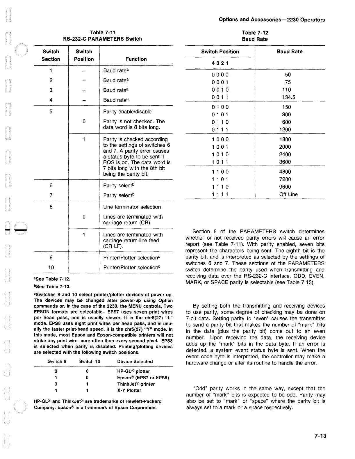
RS-232-C PARAMETERS Switch
Switch
Section
1
2
3
4
5
6
7
8
9
10
8
See Table 7-12.
bSee
Table 7-13.
Switch
Position
--
--
--
--
0
1
0
1
Function
Baud ratea
Baud ratea
Baud ratea
Baud ratea
Parity enable/disable
Parity is not checked. The
data word is 8 bits long.
Parity is checked according
to the settings
of
switches 6
and
7.
A parity error causes
a status byte to
be
sent if
RQS is on. The data word
is
7 bits long with the 8th bit
being the parity bit.
Parity selectb
Parity selectb
Line terminator selection
Lines are terminated with
carriage return
{CR).
Lines are terminated with
carriage return-line
feed
{CR-LF).
Printer/Plotter selectionc
Printer/Plotter selectionc
cswitches 9 and
10
select printer/plotter devices at power
up.
The devices
may
be changed after power-up
using
Option
commands
or,
in
the case
of
the 2230, the
MENU
controls. Two
EPSON
formats are selectable.
EPS7
uses seven print wires
per head pass, and
is
usually slower. It
is
the chr$(27)
"L"
mode.
EPSB
uses eight print wires per head pass, and
is
usu-
ally the faster print-head speed. It
is
the chr$(27) "Y" mode.
In
this mode, most Epson
and
Epson-compatible printers
will
not
strike
any
print wire more often than every second pixel.
EPSB
is
selected when parity
is
disabled. Printing/plotting devices
are selected
with
the following switch positions:
Switch 9 Switch 10
Device Selected
0
0
HP-GL@
plotter
1 0
Epson@
(EPS7 or
EPSB)
0 1 ThinkJet@ printer
1
1 X-Y Plotter
HP-GL® and ThinkJet@ are trademarks
of
Hewlett-Packard
Company.
Epson@
is a trademark
of
Epson Corporation.
Options and
Accessories-2230
Operators
Table 7-12
Baud Rate
Switch Position Baud Rate
4321
0000
50
0001
75
0 0 1 0 110
0 0 1 1 134.5
0 1 0 0 150
0 1 0 1 300
0 1 1 0 600
0 1 1 1 1200
1 0 0 0 1800
1 0 0 1 2000
1 0 1 0 2400
1 0 1 1
3600
1 1 0 0 4800
1 1 0 1 7200
1 1 1 0
9600
1 1 1 1 Off Line
Section 5 of the PARAMETERS switch determines
whether or not received parity errors will cause
an
error
report
{see
Table 7-11). With parity enabled, seven bits
represent the characters being sent. The eighth bit is the
parity bit,
and
is interpreted
as
selected by the settings of
switches 6
and
7.
These sections
of
the PARAMETERS
switch determine the parity used when transmitting
and
receiving data over the RS-232-C interface. ODD, EVEN,
MARK, or SPACE parity is selectable
{see
Table 7-13).
By setting both the transmitting
and
receiving devices
to use parity, some degree
of
checking may
be
done
on
7-bit data. Setting parity to "even" causes the transmitter
to send a parity bit that makes the number
of
"mark" bits
in
the data {plus the parity bit) come out to
an
even
number. Upon receiving the data, the receiving device
adds up the "mark" bits
in
the data byte. If
an
error is
detected, a system event status byte is sent. When the
event code byte
is
interpreted, the controller may make a
hardware change or alter its routine to handle the error.
"Odd" parity works
in
the same way, except that the
number of "mark" bits
is
expected to
be
odd. Parity may
also
be
set to "mark" or "space" where the parity bit
is
always set to a mark or a space respectively.
7-13

 Loading...


