Applications Guide
101
20.1.2 Installed Bushings
Overall Test (Centre Conductor to Flange)
If a bushing is mounted on an equipment, the overall measurement method would include all conduction and
insulation elements connected between the bushing center conductor and ground. Therefore the overall method is
not recommended for separate tests on bushings, unless the bushing conductor can be completely isolated or the
bushing has no tap.
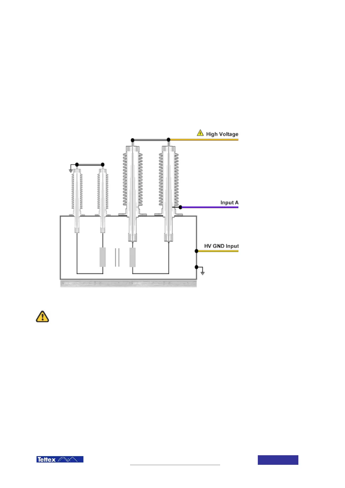
Center Conductor to Tap, C1
Most high-voltage condenser-type bushings are equipped with either potential or power-factor test taps. These
permit separate tests on the main bushing insulation (commonly referred to as C1) without the need to disconnect
a bushing from the equipment or bus to which it is connected.
The C1 insulation is
measured by the UST A
mode. The connection
is shown in the figure
beside.
The values are
measured in the
conventional manner,
and the dissipation
factor is calculated and
corrected for
temperature. For a
bushing in a power or
distribution transformer
the average
temperature of the
transformer top-oil and
ambient air temperature
should be used. For
bushings mounted in oil
circuit breakers the C1
dissipation factor should
be corrected using the
air temperature.
C1 Insulation test of bushing in transformer
During measurements on bushings in transformers, all terminals of the windings to
which the bushings are connected must be tied together electrically. Otherwise
higher-than-normal losses may be recorded due to the influence of the winding
inductance. Also, for safety the bushings associated with all windings not energized
should be grounded and not left floating.
Tap-Insulation Test (Tap to Flange, C2)
Before starting any measurements the test engineer must carefully consider the type of tap and its corresponding
maximum rated voltage. The maximum permissible test voltage is usually designated by the manufacturer
(generally between 500 V and 2 kV).
 Loading...