Functional Description
17
6 Functional Description
6.1 System Overview
To be able to execute correct and reproducible measurements it is essential to understand
how the MIDAS micro 2883 measuring system works.
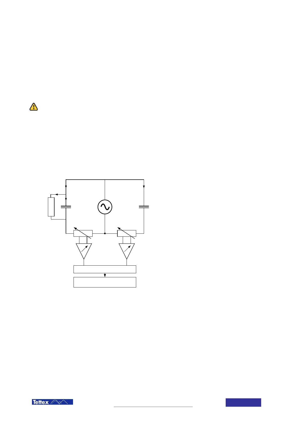
The MIDAS measuring system is based on the double vector-meter method which relies upon the measurement of
the current I
N
through the known reference capacitor C
N
and the measurement of the current I
X
through the
unknown test object C
X
.
Both branches are energized by the built-in HV AC power source (U
Test
) and both currents are measured by the
adjustable high accurate shunts R
X
and R
N
and then digitised. The digitised data streams are fed into a CPU and
by comparison of the two measured currents and knowing the exact values of the standard capacitor all other
desired measuring values can now be determined.
ADC
Digital Signal Processing
I
Rx
I
Cx
I
X
I
N
High Voltage
U
Test
C
N
C
X
R
X
R
N
V
U
X
~ I
X
U
N
~ I
N
Functional Schematics
I
X
Current trough Device Under Test C
X
I
N
Current trough known Standard
Capacitor C
N
I
RX
Losses of the Device Under Test C
X
C
X
Test Object (ideal capacitance)
C
N
Standard capacitor (with tan δ < 10
-5
)
R
X
Measuring shunt for I
X
, C
X
R
N
Measuring shunt for I
N
, C
N
Differential Amplifiers
ADC Analogue to Digital Converter
6.2 V-potential point and Guarding
This measuring system is able to measure capacitances with highest accuracy to determine trending analysis of
insulating materials. In the range of normal insulation capacitances the always existent stray capacitances -
measured together with the DUT - are influencing the measuring values significantly. So these unwanted stray
capacitance effects have to be eliminated.
This is realized by the so called “guarding” of the relevant elements. That means that the complete high voltage
source, the supply and measuring cables have to be shielded with the so called “V-potential” which is the low
voltage point (reference) of the high voltage supply. All capacitances connected to this reference point are
bypassed and are therefore not influencing the measuring value. Due to this guarding concept the supplied
shielded coax measuring cables (for High Voltage Supply, Input A and Input B) have to be used always. If the
system is connected with normal unshielded cables the measuring values will be incorrect.